ATTACHING CHUTE MOTOR
WIRING HARNESS
1.Wiring Harness is in four (4) parts.
a.Switch
b.Upper wiring harness with main power connector
c.Final wiring harness with a square connector on each end.
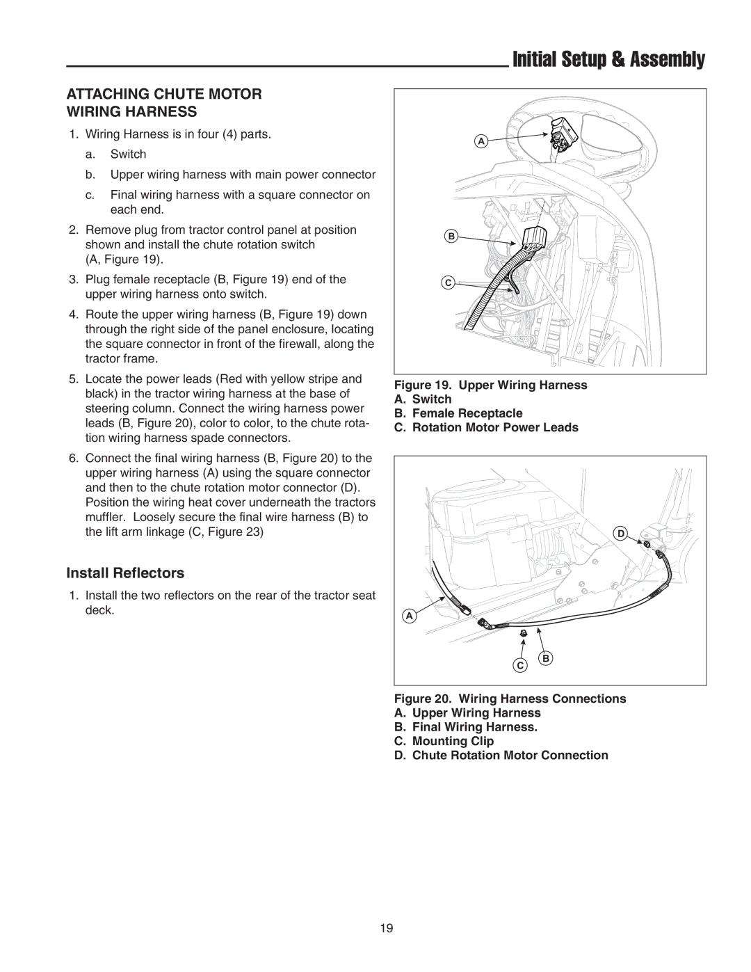
2.Remove plug from tractor control panel at position shown and install the chute rotation switch
(A, Figure 19).
3.Plug female receptacle (B, Figure 19) end of the upper wiring harness onto switch.
4.Route the upper wiring harness (B, Figure 19) down through the right side of the panel enclosure, locating the square connector in front of the firewall, along the tractor frame.
5.Locate the power leads (Red with yellow stripe and black) in the tractor wiring harness at the base of steering column. Connect the wiring harness power leads (B, Figure 20), color to color, to the chute rota- tion wiring harness spade connectors.
6.Connect the final wiring harness (B, Figure 20) to the upper wiring harness (A) using the square connector and then to the chute rotation motor connector (D).
Position the wiring heat cover underneath the tractors muffler. Loosely secure the final wire harness (B) to the lift arm linkage (C, Figure 23)
Install Reflectors
1.Install the two reflectors on the rear of the tractor seat deck.
Initial Setup & Assembly
A |
B |
C |
Figure 19. Upper Wiring Harness
A.Switch
B.Female Receptacle
C.Rotation Motor Power Leads
D |
A |
B |
C |
Figure 20. Wiring Harness Connections
A.Upper Wiring Harness
B.Final Wiring Harness.
C.Mounting Clip
D.Chute Rotation Motor Connection
19