Initial Setup & Assembly
8.Rotate the belt tension lever upwards into the locked position (B, Figure 15), fully tensioning the snow thrower drive belt.
NOTE: Do not connect the mower deck lift arm or cable to the belt tension lever.
ATTACHING LIFT ARM ASSEMBLY TO TRACTOR
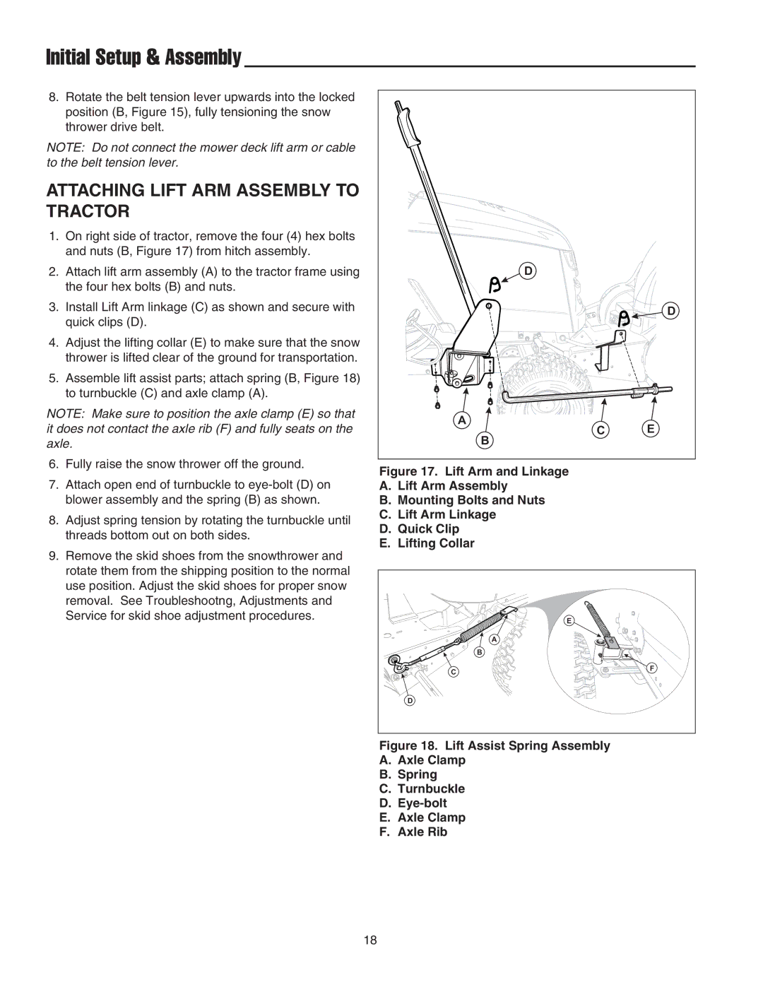
1.On right side of tractor, remove the four (4) hex bolts and nuts (B, Figure 17) from hitch assembly.
2.Attach lift arm assembly (A) to the tractor frame using the four hex bolts (B) and nuts.
3.Install Lift Arm linkage (C) as shown and secure with quick clips (D).
4.Adjust the lifting collar (E) to make sure that the snow thrower is lifted clear of the ground for transportation.
5.Assemble lift assist parts; attach spring (B, Figure 18) to turnbuckle (C) and axle clamp (A).
NOTE: Make sure to position the axle clamp (E) so that it does not contact the axle rib (F) and fully seats on the axle.
6.Fully raise the snow thrower off the ground.
7.Attach open end of turnbuckle to
8.Adjust spring tension by rotating the turnbuckle until threads bottom out on both sides.
9.Remove the skid shoes from the snowthrower and rotate them from the shipping position to the normal use position. Adjust the skid shoes for proper snow removal. See Troubleshootng, Adjustments and Service for skid shoe adjustment procedures.
D |
|
| D |
A | E |
C | |
B |
|
Figure 17. Lift Arm and Linkage
A.Lift Arm Assembly
B.Mounting Bolts and Nuts
C.Lift Arm Linkage
D.Quick Clip
E.Lifting Collar
| E |
| A |
| B |
C | F |
| |
D |
|
Figure 18. Lift Assist Spring Assembly
A.Axle Clamp
B.Spring
C.Turnbuckle
D.Eye-bolt
E.Axle Clamp
F.Axle Rib
18