CDX-GT21W/GT210/GT260/GT260S
Ver. 1.2
• E model
This label is located on the bottom of the chassis.
• Chinese model
NOTE FOR REPLACEMENT OF THE SERVO BOARD
When repairing, the complete SERVO board
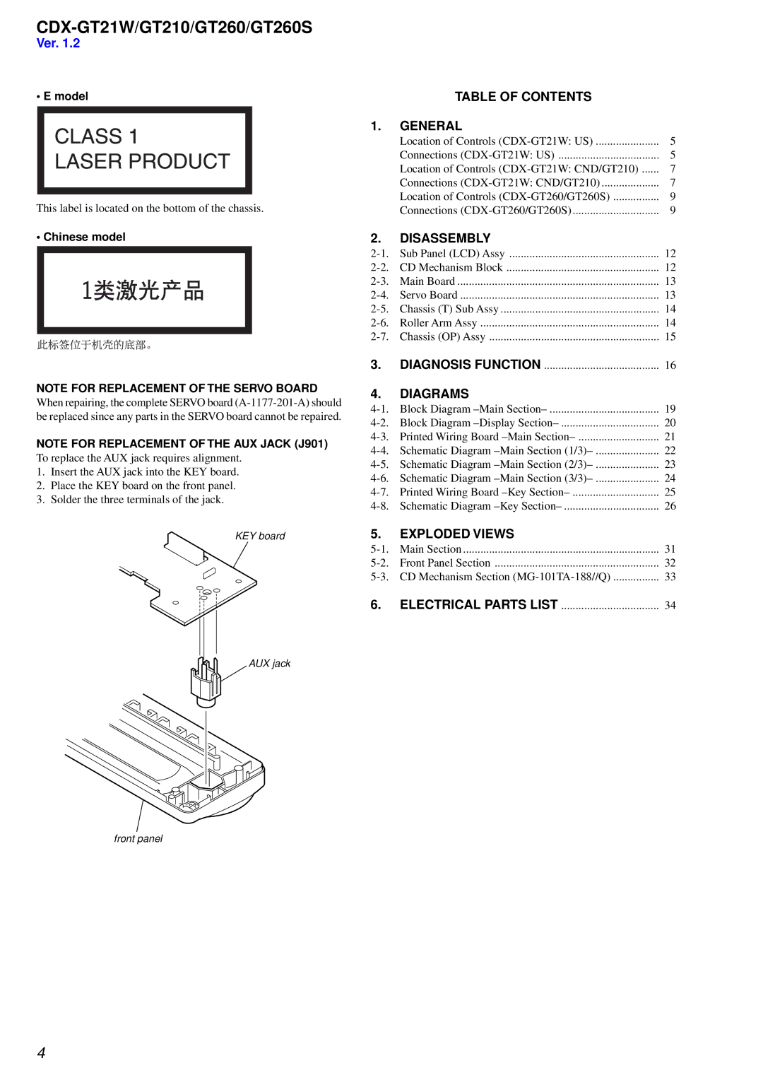
NOTE FOR REPLACEMENT OF THE AUX JACK (J901)
To replace the AUX jack requires alignment.
1.Insert the AUX jack into the KEY board.
2.Place the KEY board on the front panel.
3.Solder the three terminals of the jack.
KEY board
AUX jack
front panel
TABLE OF CONTENTS |
|
1. GENERAL |
|
Location of Controls | 5 |
Connections | 5 |
Location of Controls | 7 |
Connections | 7 |
Location of Controls | 9 |
Connections | 9 |
2.DISASSEMBLY
Sub Panel (LCD) Assy | 12 | |
CD Mechanism Block | 12 | |
Main Board | 13 | |
Servo Board | 13 | |
Chassis (T) Sub Assy | 14 | |
14 | ||
Chassis (OP) Assy | 15 | |
3. | DIAGNOSIS FUNCTION | 16 |
4.DIAGRAMS
19 | ||
20 | ||
21 | ||
22 | ||
Schematic Diagram | 23 | |
Schematic Diagram | 24 | |
Printed Wiring Board | 25 | |
Schematic Diagram | 26 | |
5.EXPLODED VIEWS
Main Section | 31 | |
Front Panel Section | 32 | |
CD Mechanism Section | 33 | |
6. | ELECTRICAL PARTS LIST | 34 |
4