NOTE: Follow the disassembly procedure in the numerical order given.
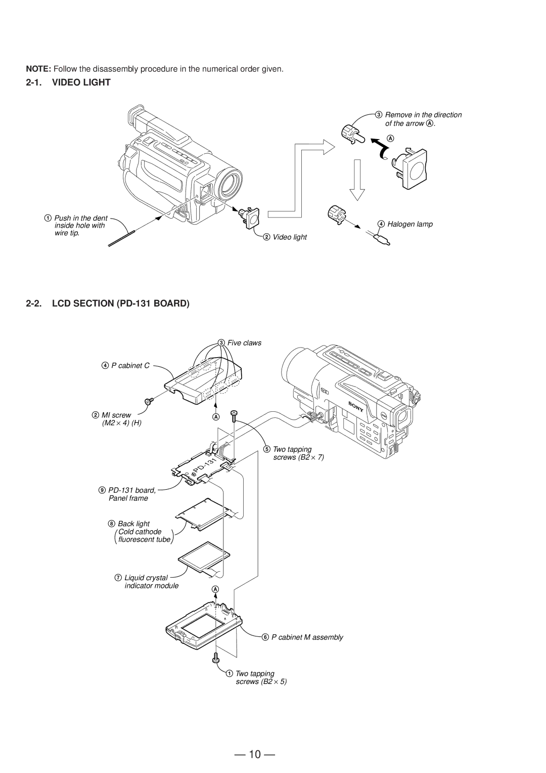
2-1. VIDEO LIGHT
3 Remove in the direction of the arrow A.
A
1 Push in the dent | 4 Halogen lamp |
inside hole with | |
wire tip. | 2 Video light |
|
2-2. LCD SECTION (PD-131 BOARD)
4P cabinet C
2MI screw (M2 ⋅ 4) (H)
9
8 Back light Cold cathode fluorescent tube
7 Liquid crystal indicator module
3Five claws
A
5 Two tapping screws (B2 ⋅ 7)
A
6 P cabinet M assembly
1Two tapping screws (B2 ⋅ 5)
— 10 —