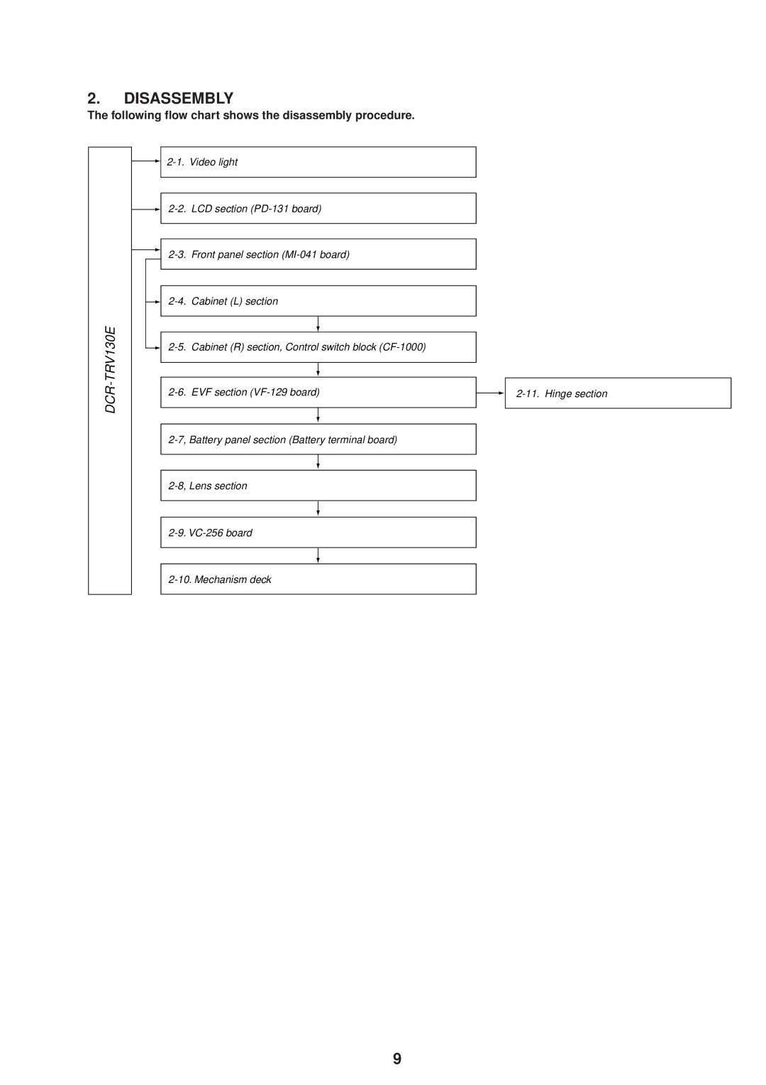
2-1. Video light
2-2. LCD section (PD-131 board)
2-3. Front panel section (MI-041 board)
2-4. Cabinet (L) section
TRV130E-
2-5.
Cabinet (R) section, Control switch block (CF-1000)
2-6.
EVF section (VF-129 board)
2-7, Battery panel section (Battery terminal board)
2-8, Lens section
2-9. VC-256 board
2-10. Mechanism deck
2-11. Hinge section
— 9 —