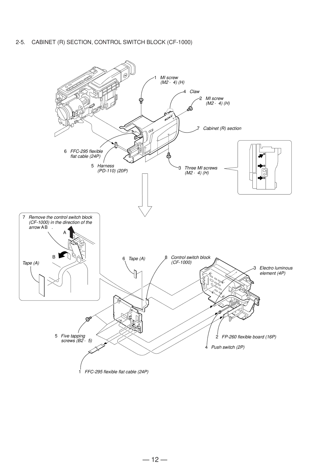
2-5. CABINET (R) SECTION, CONTROL SWITCH BLOCK (CF-1000)
6
5 Harness
7Remove the control switch block
A
1MI screw (M2 ⋅ 4) (H)
4Claw
2 MI screw
(M2 ⋅ 4) (H)
7 Cabinet (R) section
3Three MI screws (M2 ⋅ 4) (H)
B | 6 Tape (A) | 8 Control switch block |
Tape (A) |
|
3 Electro luminous element (4P)
5 Five tapping | 2 |
screws (B2 ⋅ 5) |
|
| 4 Push switch (2P) |
1
— 12 —
