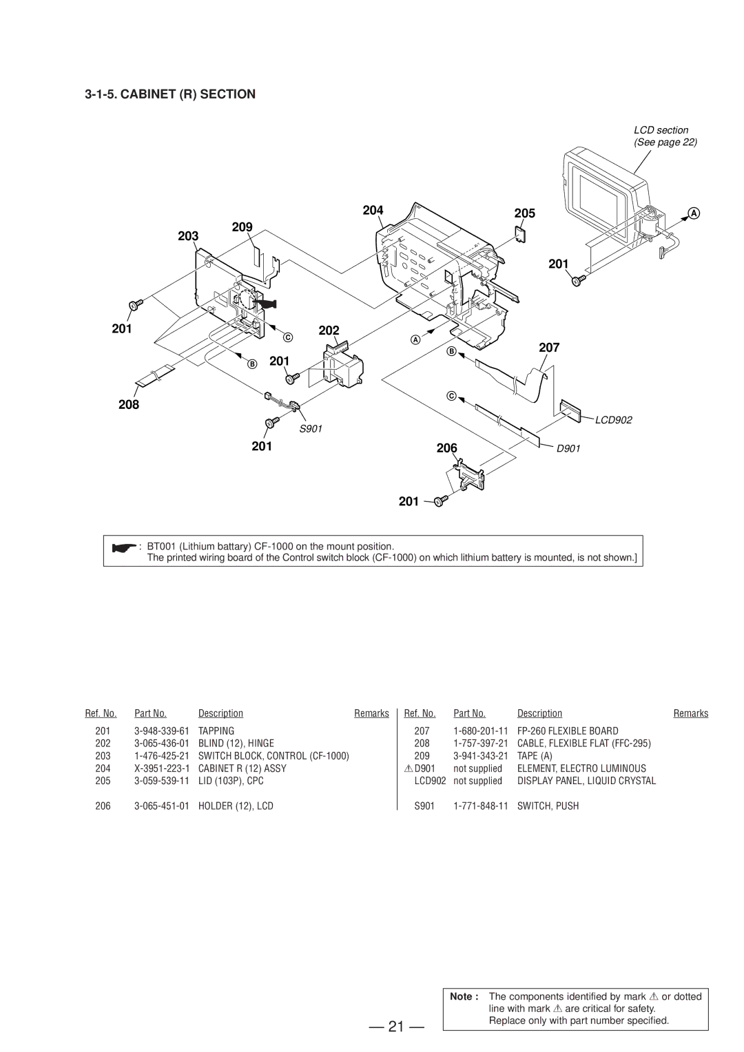
3-1-5. CABINET (R) SECTION
LCD section (See page 22)
204 | 205 | A |
209
203
201
201 | 202 |
|
C | A | 207 |
B 201 | B | |
|
| |
208 | C |
|
|
| |
| S901 | LCD902 |
|
| |
201 | 206 | D901 |
201
![]() : BT001 (Lithium battary)
: BT001 (Lithium battary)
The printed wiring board of the Control switch block
Ref. No. | Part No. | Description | Remarks Ref. No. | Part No. | Description | Remarks |
201 | TAPPING | 207 |
| |||
202 | BLIND (12), HINGE | 208 | CABLE, FLEXIBLE FLAT |
| ||
203 | SWITCH BLOCK, CONTROL | 209 | TAPE (A) |
| ||
204 | CABINET R (12) ASSY | 0D901 | not supplied | ELEMENT, ELECTRO LUMINOUS |
| |
205 | LID (103P), CPC | LCD902 | not supplied | DISPLAY PANEL, LIQUID CRYSTAL |
|
206 |
S901
— 21 —
Note : The components identified by mark 0or dotted line with mark 0are critical for safety.
Replace only with part number specified.
