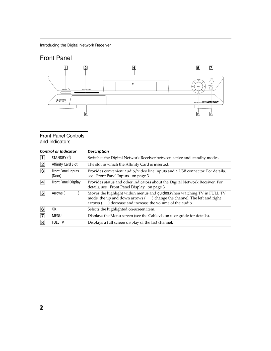
DHG-M55CV specifications
The Sony DHG-M55CV is an innovative digital hybrid terrestrial and cable HD DVR designed to enhance your viewing experience and revolutionize how you interact with television content. This device became popular for merging traditional broadcast TV with the modern demands of digital recording and playback, making it an essential piece of equipment for any serious home entertainment system.At the heart of the DHG-M55CV is its ability to receive both over-the-air broadcasts and cable signals, delivering a wide range of content without the need for multiple devices. The dual-tuner system allows users to watch one show while recording another simultaneously, ensuring that you never miss your favorite programs. With the capacity to store a generous amount of high-definition content, the built-in hard drive caters to binge-watching and allows users to keep their essential shows at their fingertips.
A standout feature of the DHG-M55CV is its user-friendly interface that simplifies navigation through recorded shows, live TV, and the extensive program guide. The intuitive design makes it easy for users to manage their viewing schedules effectively. Working seamlessly with various recording settings, the device supports one-touch recording, which facilitates instant capturing of live broadcasts with minimal hassle.
Additionally, the Sony DHG-M55CV incorporates advanced video processing technologies that enhance image quality. This includes features designed to upscale standard-definition content to near-HD quality, ensuring that viewers can enjoy a superior visual experience regardless of the source material. Coupled with Dolby Digital audio support, it provides immersive sound quality that complements the stunning visuals.
The device's connectivity options further enhance its versatility, enabling users to connect it to other devices, such as home theater systems and external storage for further expansion of its recording capabilities. Ethernet connectivity also allows for potential network streaming services, although the primary focus remains on live and recorded television.
The design of the DHG-M55CV is sleek and fits well within modern entertainment setups. Its relatively compact dimensions make it easy to integrate into existing furniture arrangements. As a combination of innovative technology and user-centric features, the Sony DHG-M55CV remains a significant player in the evolution of home media consumption. Up to date and well-equipped for modern viewing habits, it offers a combination of functionality and convenience that speaks directly to today’s audiences.

