SECTION 2: SET-UP ADJUSTMENTS
The following adjustments should be made when a complete | Perform the adjustments in order as follows: | ||
realignment is required or a new picture tube is installed. | 1. | Beam Landing | |
These adjustments should be performed with rated power supply | 2. | Convergence | |
3. | Focus | ||
voltage unless otherwise noted. | 4. | Screen (G2) | |
Set the controls as follows unless otherwise noted: | 5. | White Balance | |
Note Test Equipment Required: | |||
VIDEO MODE: Standard | 1. | Color Bar Pattern Generator | |
PICTURE CONTROL: Normal | 2. | Degausser | |
BRIGHTNESS CONTROL: Normal | 3. | DC Power Supply | |
| 4. | Digital Multimeter | |
|
| ||
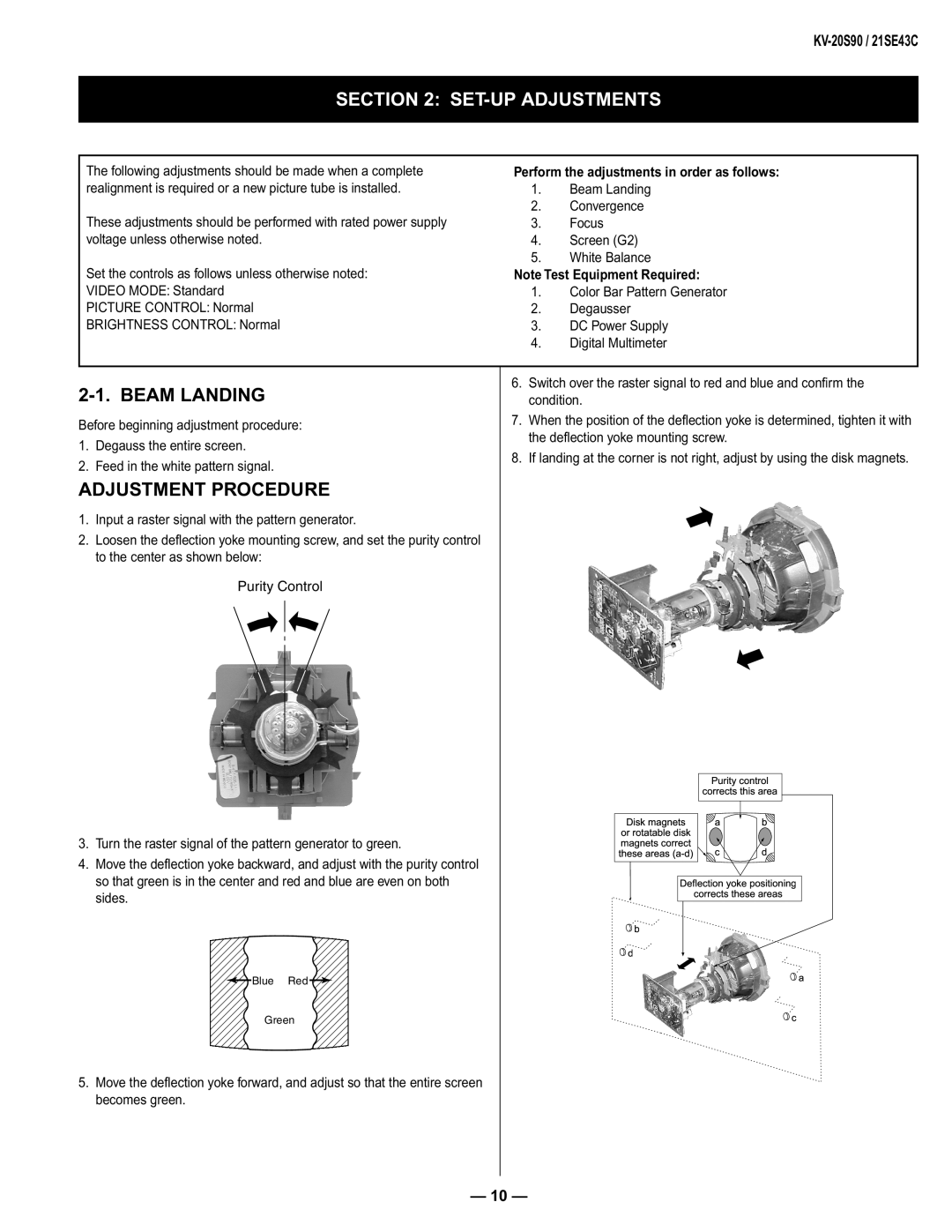
| 6. Switch over the raster signal to red and blue and confi rm the | ||
condition. | |||
Before beginning adjustment procedure: | 7. When the position of the defl ection yoke is determined, tighten it with | ||
the defl ection yoke mounting screw. | |||
1. Degauss the entire screen. | |||
8. If landing at the corner is not right, adjust by using the disk magnets. | |||
2. Feed in the white pattern signal. | |||
|
| ||
ADJUSTMENT PROCEDURE |
|
| |
1. Input a raster signal with the pattern generator.
2.Loosen the defl ection yoke mounting screw, and set the purity control to the center as shown below:
Purity Control
| orDiskrotatablemagnetsdik | correctsPuritycontrolthisarea |
| ||
| a | b |
| ||
| db |
| correctstheseareas |
| |
3. Turn the raster signal of the pattern generator to green. |
|
| d |
| |
|
| ||||
4. Move the defl ection yoke backward, and adjust with the purity control |
| Deflectionyokepositioning |
| ||
so that green is in the center and red and blue are even on both |
| a | |||
sides. |
|
|
| c | |
|
|
|
| ||
Blue Red |
|
|
|
| |
|
|
|
|
| |
Green |
|
|
|
|
|
5.Move the defl ection yoke forward, and adjust so that the entire screen becomes green.
— 10 —