7. INITIAL SETTING OF ADJUSTMENT VALUE

Note:

Mode which sets the adjustment results recorded in the non-volatile memory to the initial setting value. However the results of the tempera- ture compensation offset adjustment will not change to the initial setting value.

If initial setting is performed, perform all adjustments again excluding the temperature compensation offset adjustment.

For details of the initial setting, refer to “4. Precautions for Adjustments” and execute the initial setting before the adjustment as required.

Setting Procedure :

1.Turn the [ÊÊÊÊÊÊÊÊAMSÊÊÊÊÊÊÊÊ]- ± knob to display “ADJ CLEAR” (C24).

2.Press the [YES] button. “Complete!” will be displayed mo- mentarily and initial setting will be executed, after which “ADJ CLEAR” will be displayed.

8. RECORDING AND DISPLAYING THE IOP INFORMATION

The IOP data can be recorded in the non-volatile memory. The IOP value on the optical pick-up label and the IOP value after the adjustment will be recorded. Recording these data eliminates the need to read the label on the optical pick-up.

Recording Procedure :

1.Turn the [ÊÊÊÊÊÊÊÊAMSÊÊÊÊÊÊÊÊ]- ± knob to display “Iop Write” (C28), and press the [YES] button.

2.The display becomes Ref=@@@.@ (@ is an arbitrary num- ber) and the numbers which can be changed will blink.

3.Input the IOP value on the optical pick-up label.

To select the number : Turn the [ÊÊÊÊÊÊÊÊAMSÊÊÊÊÊÊÊÊ]- ± knob.

To select the digit : Press the [ÊÊÊÊÊÊÊÊAMSÊÊÊÊÊÊÊÊ]- ± knob

4.When the [YES] button is pressed, the display becomes “Measu=@@@.@” (@ is an arbitrary number).

5.As the adjustment results are recorded for the 6 value. Leave it as it is and press the [YES] button.

6.“Complete!” will be displayed momentarily. The value will be recorded in the non-volatile memory and the display will be- come “Iop Write”.

Display Procedure :

1.Turn the [ÊÊÊÊÊÊÊÊAMSÊÊÊÊÊÊÊÊ]- ± knob to display “Iop Read”(C27).

2.“@@.@/##.#” is displayed and the recorded contents are dis- played.

@@.@ indicates the IOP value on the optical pick-up label. ##.# indicates the IOP value after adjustment

3.To end, press the [ÊÊÊÊÊÊÊÊAMSÊÊÊÊÊÊÊÊ]- ± button or [MENU/NO] button to display “Iop Read”.

9. TEMPERATURE COMPENSATION OFFSET ADJUSTMENT

Save the temperature data at that time in the non-volatile memory as 25 ˚C reference data.

Note :

1.Usually, do not perform this adjustment.

2.Perform this adjustment in an ambient temperature of 22 ˚C to 28 ˚C. Perform it immediately after the power is turned on when the internal temperature of the unit is the same as the ambient temperature of 22 ˚C to 28 ˚C.

3.When D101 has been replaced, perform this adjustment after the tem- perature of this part has become the ambient temperature.

Adjusting Procedure :

1.Turn the [ÊÊÊÊÊÊÊÊAMSÊÊÊÊÊÊÊÊ]- ± knob to display “TEMP ADJUS” (C09).

2.Press the [YES] button to select the “TEMP ADJUS” mode.

3.“TEMP = [OK” and the current temperature data will be displayed.

4.To save the data, press the [YES] button.

When not saving the data, press the [MENU/NO] button.

5.When the [YES] button is pressed, “TEMP = SAVE” will be displayed and turned back to “TEMP ADJUS” display then. When the [MENU/NO] button is pressed, “TEMP ADJUS” will be displayed immediately.

Specified Value :

The “TEMP = ” should be within “E0 - EF”, “F0 - FF”, “00 - 0F”, “10 - 1F” and “20 - 2F”.

10. LASER POWER ADJUSTMENT

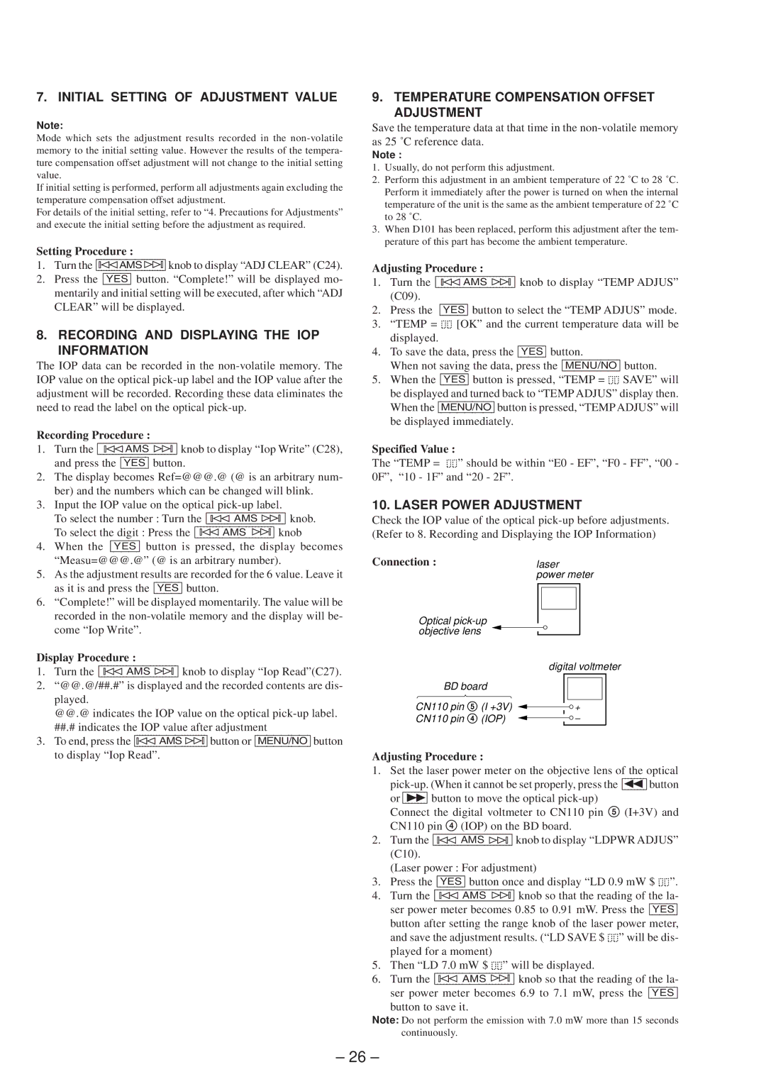
Check the IOP value of the optical pick-up before adjustments. (Refer to 8. Recording and Displaying the IOP Information)

Connection :laser power meter

Optical pick-up objective lens

digital voltmeter

BD board


CN110 pin 5

(I +3V)


+


CN110 pin 4

(IOP)


Adjusting Procedure :

1.Set the laser power meter on the objective lens of the optical pick-up. (When it cannot be set properly, press the [ÊÊÊÊÊÊ]0 button or [ÊÊÊÊÊÊ]) button to move the optical pick-up)

Connect the digital voltmeter to CN110 pin 5 (I+3V) and CN110 pin 4 (IOP) on the BD board.

2.Turn the [ÊÊÊÊÊÊÊÊAMSÊÊÊÊÊÊÊÊ]- ± knob to display “LDPWR ADJUS” (C10).

(Laser power : For adjustment)

3.Press the [YES] button once and display “LD 0.9 mW $ ”.

4.Turn the [ÊÊÊÊÊÊÊÊAMSÊÊÊÊÊÊÊÊ]- ± knob so that the reading of the la- ser power meter becomes 0.85 to 0.91 mW. Press the [YES] button after setting the range knob of the laser power meter, and save the adjustment results. (“LD SAVE $ ” will be dis- played for a moment)

5.Then “LD 7.0 mW $ ” will be displayed.

6.Turn the [ÊÊÊÊÊÊÊÊAMSÊÊÊÊÊÊÊÊ]- ± knob so that the reading of the la- ser power meter becomes 6.9 to 7.1 mW, press the [YES]

button to save it.

Note: Do not perform the emission with 7.0 mW more than 15 seconds continuously.

– 26 –

Page 26
Image 26
Sony MDS-JE630 Initial Setting of Adjustment Value, Recording and Displaying the IOP Information, Laser Power Adjustment

MDS-JE630 specifications

The Sony MDS-JE630 is a compact and versatile MiniDisc recorder that was launched in the late 1990s, showcasing Sony's commitment to portable digital audio technology. Renowned for its superior sound quality, the MDS-JE630 is an exceptional choice for audiophiles and professionals alike, offering a user-friendly interface and a range of advanced features.

One of the main highlights of the MDS-JE630 is its MDLP (MiniDisc Long Play) technology, which allows for extended recording time without sacrificing audio quality. This feature enables users to record up to 148 minutes of stereo sound on a single MiniDisc, making it an invaluable tool for those requiring longer recording sessions, such as musicians or radio broadcasters.

The MDS-JE630 is equipped with ATRAC (Adaptive Transform Acoustic Coding) compression algorithms, ensuring that audio files retain high fidelity even when compressed. The device features a 20-bit digital-to-analog converter, providing remarkable sound clarity and depth. Users can expect crisp highs and robust lows, making every listening experience engaging and immersive.

Ease of use is another hallmark of the MDS-JE630. The front panel includes an intuitive layout, featuring a large LCD display that clearly shows current track information, time elapsed, and other playback indicators. Additionally, the unit offers various playback modes such as normal, repeat, and shuffle, allowing users to customize their listening experience.

The recording process on the MDS-JE630 is seamless, thanks to its one-touch recording feature. Users can easily initiate recordings from connected sources, including CD players or turntables, via the device's multiple inputs, such as line-in and optical digital inputs. This adaptability makes it a versatile component for any audio setup, whether for home studios or live performances.

Moreover, the MDS-JE630 incorporates a variety of editing functions, including track arranging, dividing, and merging, providing users with the ability to create perfectly curated audio collections. The device also supports a wide range of MiniDisc formats, ensuring compatibility with existing media.

In conclusion, the Sony MDS-JE630 stands out as a premier MiniDisc recorder, offering a blend of advanced technology, user-friendly design, and high-quality playback. Its innovative features and commitment to sound quality have made it a popular choice for music professionals and enthusiasts, solidifying its reputation as a reliable audio recording solution for years to come.