MDS-JE770
Display |
|
|
|
|
| History |
|
|
|
|
|
| |
spdl change | Mode for erasing the total spdl rp tm time | |||||
| These histories are based on the time of replacement of the spindle motor. If the spindle motor has been replaced, | |||||
| perform this procedure and erase the history. | |||||
| Procedure | |||||
| 1. | Press the | lAMSL | knob when displayed as “spdl change” | ||
|
|
|
|
| ||
| 2. | Press the | YES | button when the display changes to “spdl change?” | ||
| When “Complete!” is displayed, it means erasure has completed. | |||||
|
|
|
|
|
|
|
Table of Error Codes
Error Code | Description |
|
|
10 | Could not load |
|
|
12 | Loading switches combined incorrectly |
|
|
20 | Timed out without reading the top of PTOC |
|
|
21 | Could read top of PTOC, but detected error |
|
|
22 | Timed out without accessing UTOC |
|
|
23 | Timed out without reading UTOC |
|
|
24 | Error in UTOC |
|
|
30 | Could not start playback |
|
|
31 | Error in sector |
|
|
40 | Retry cause generated during normal recording |
|
|
41 | Retried in DRAM overflow |
|
|
42 | Retry occurred during TOC writing |
|
|
43 | Retry aborted during S.F editing |
|
|
50 | Other than access processing, and could not read address. |
|
|
51 | Focus NG occurred and overran. |
|
|
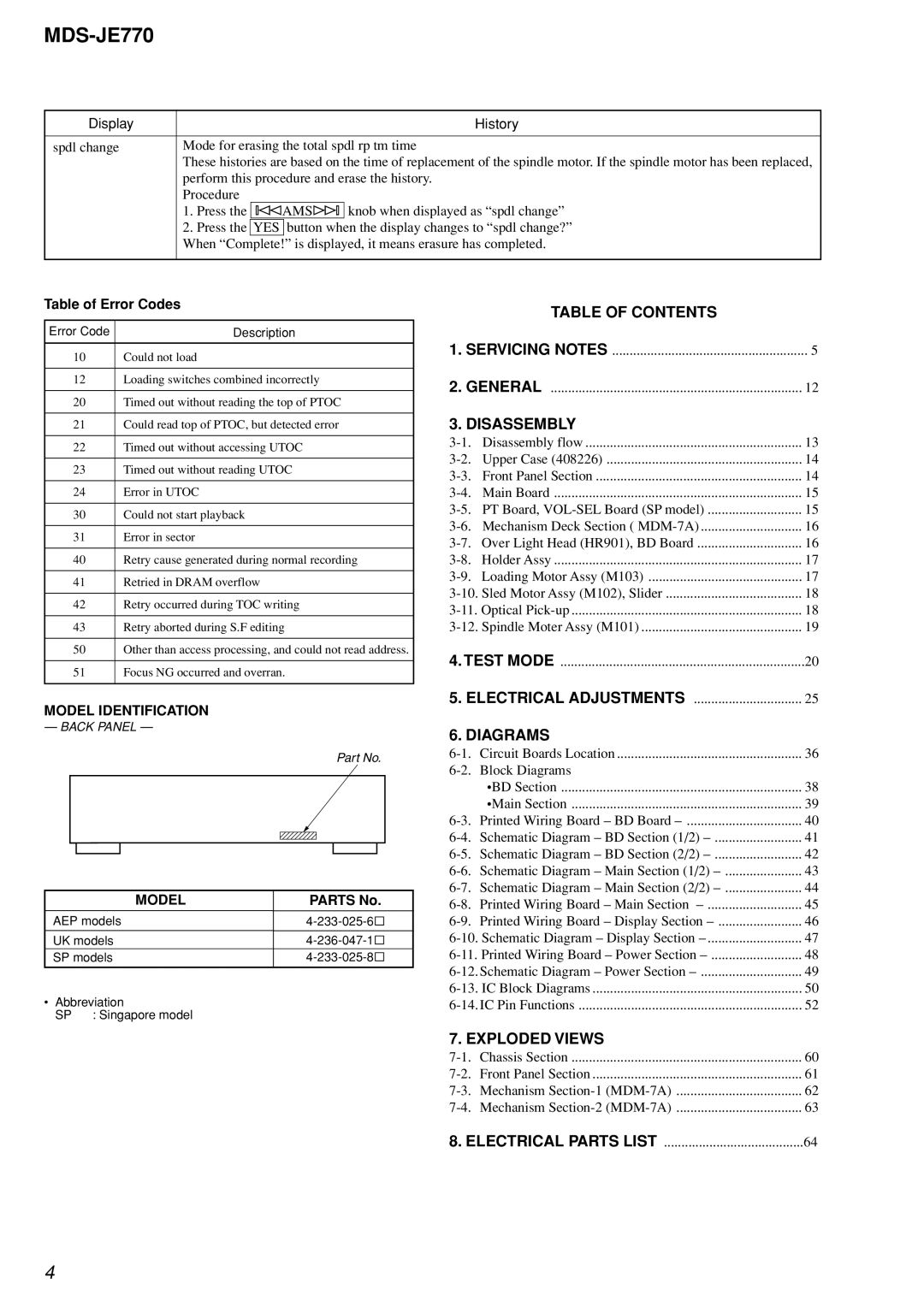
MODEL IDENTIFICATION
— BACK PANEL —
Part No.
MODEL | PARTS No. |
|
|
AEP models | |
|
|
UK models | |
SP models | |
|
|
• Abbreviation
SP : Singapore model
| TABLE OF CONTENTS |
|
1. SERVICING NOTES | 5 | |
2. GENERAL | 12 | |
3. DISASSEMBLY |
| |
Disassembly flow | 13 | |
Upper Case (408226) | 14 | |
Front Panel Section | 14 | |
Main Board | 15 | |
15 | ||
Mechanism Deck Section ( | 16 | |
Over Light Head (HR901), BD Board | 16 | |
Holder Assy | 17 | |
Loading Motor Assy (M103) | 17 | |
18 | ||
18 | ||
19 | ||
4. TEST MODE | 20 | |
5. ELECTRICAL ADJUSTMENTS | 25 | |
6. DIAGRAMS |
| |
Circuit Boards Location | 36 | |
Block Diagrams |
| |
| •BD Section | 38 |
| •Main Section | 39 |
40 | ||
41 | ||
42 | ||
43 | ||
44 | ||
Printed Wiring Board – Main Section | 45 | |
46 | ||
47 | ||
48 | ||
49 | ||
50 | ||
52 | ||
7. EXPLODED VIEWS |
| |
Chassis Section | 60 | |
Front Panel Section | 61 | |
Mechanism | 62 | |
Mechanism | 63 | |
8. ELECTRICAL PARTS LIST | 64 |
4