MZ-N505
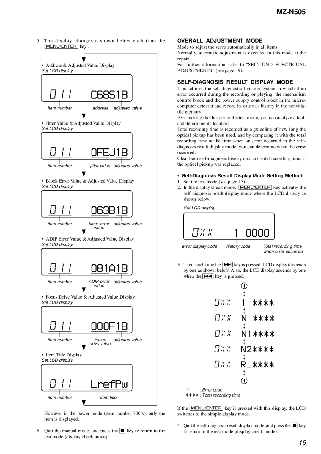
5.The display changes a shown below each time the
[MENU/ENTER] key .
•Address & Adjusted Value Display
Set LCD display
011C68S1B
|
|
|
|
|
|
|
|
|
|
|
|
|
|
|
|
|
|
|
|
|
|
item number |
| address adjusted value | ||||||||
|
|
|
|
|
|
|
|
|
|
|
•Jitter Value & Adjusted Value Display
Set LCD display
0110FEJ1B
|
|
|
|
|
|
|
|
|
|
|
|
|
|
|
|
|
|
|
|
|
|
item number | jitter value adjusted value | |||||||||
|
|
|
|
|
|
|
|
|
|
|
•Block Error Value & Adjusted Value Display
Set LCD display
011063B1B
|
|
|
|
|
|
|
|
|
|
|
|
|
|
|
|
|
|
|
|
|
|
item number | block error adjusted value | |||||||||
|
|
|
|
| value | |||||
•ADIP Error Value & Adjusted Value Display
Set LCD display
011081A1B
|
|
|
|
|
|
|
|
|
|
|
|
|
|
|
|
|
|
|
|
|
|
item number | ADIP error adjusted value | |||||||||
|
|
|
|
| value | |||||
•Focus Drive Value & Adjusted Value Display
Set LCD display
011000F1B
|
|
|
|
|
|
|
|
|
|
|
|
|
|
|
|
|
|
|
|
|
|
|
|
item number |
| Focus | adjusted value | ||||||||
|
|
|
| drive value |
|
|
|
| |||
•Item Title Display
Set LCD display
011LrefPw
|
|
|
|
|
|
|
|
|
|
|
|
|
|
item number |
| item title | ||||
|
|
|
|
|
|
|
However in the power mode (item number 700’s), only the item is displayed.
6.Quit the manual mode, and press the x key to return to the test mode (display check mode).
OVERALL ADJUSTMENT MODE
Mode to adjust the servo automatically in all items.
Normally, automatic adjustment is executed in this mode at the repair.
For further information, refer to “SECTION 5 ELECTRICAL ADJUSTMENTS” (see page 19).
SELF-DIAGNOSIS RESULT DISPLAY MODE
This set uses the
By checking this history in the test mode, you can analyze a fault and determine its location.
Total recording time is recorded as a guideline of how long the optical pickup has been used, and by comparing it with the total recording time at the time when an error occurred in the self- diagnosis result display mode, you can determine when the error occurred.
Clear both
•Self-Diagnosis Result Display Mode Setting Method
1. Set the test mode (see page 13).
2. In the display check mode, [MENU/ENTER] key activates the
Set LCD display
| 0XX | 1 0000 | |||||||||
|
|
|
|
|
|
|
|
|
|
|
|
|
|
|
|
|
|
|
|
|
| ||
error display code | history code |
| Total recording time | ||||||||
| |||||||||||
|
|
|
|
|
|
|
|
|
| when error occurred | |
3.Then, each time the > key is pressed, LCD display descends by one as shown below. Also, the LCD display ascends by one when the . key is pressed.
1
0XX 1 ****
0XX N ****
0XX N1****
0XX N2****
0XX R_****
1
XX: Error code
** * * : Total recording time
If the [MENU/ENTER] key is pressed with this display, the LCD switches to the simple display mode.
4.Quit the
15