Contents
NEW
Specifications
LCX-2R
Flexible Circuit Board Repairing
Table of Contents
Diagrams
Exploded Views Electrical Parts List
Eeprom
Section Servicing Notes
Location of Controls
Headphones with a remote control RM-MZ2S
Section
General
Panel ASSY, Bottom
Section Disassembly
Upper Panel Section
MZ-R90
LCD MODULE, BUTTON, CONTROL, Service ASSY, Upper Panel
MZ-R91
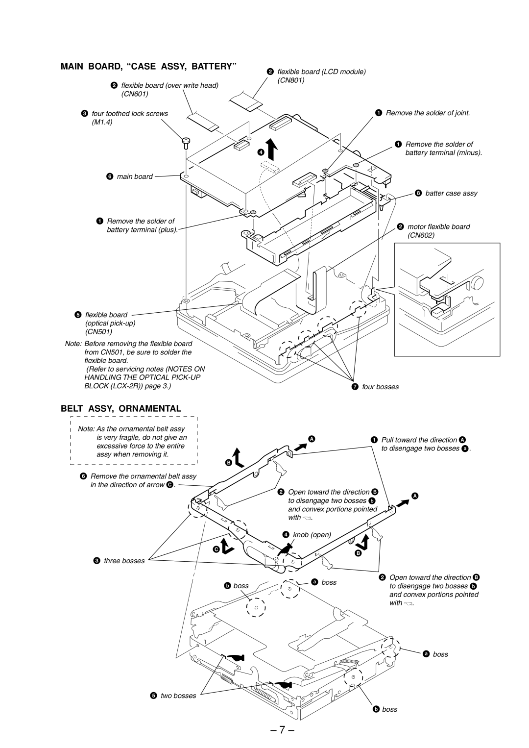
Belt ASSY, Ornamental
Main BOARD, Case ASSY, Battery
Chassis ASSY, SET, MD Mechanism Deck MT-MZR90-165
Service ASSY, OP
Motor Flexible Board
Holder Assy
MOTOR, DC Sled M602
Releasing the Test Mode
Test Mode
Setting Method of Test Mode
Operation in Setting the Test Mode
Manual Mode
Configuration of Test Mode
A n u a l
011 0 5 9 a 0
Overall Adjustment Mode
011 0 F F J 0
011 0 6 3 B 0
T r y
Sound Skip Check Result Display Mode
Setting method of Sound Skip Check Result Display Mode
T a t
000 1 s t
Self-Diagnosis Display Mode
REC
Description of Error Indication Codes
Clearing Self-Diagnosis Data and Total Recording Time
Description of Indication History
Key Indication
Key Check Mode
E s
Section Electrical Adjustments
E s N
E s O K ?
R h V c h
C l P W M
C h P W M
R h V c l
D O K
E t T m p
S S Y
D R U N
E s C l r
Laser Power Check
O O K
E s u m e
REC Digital
Section Diagrams
Block Diagram Servo Section
Signal Path
Block Diagram KEY CONTROL/DISPLAY/POWER Supply Section
Block Diagram A/D, D/A CONVERTER, Audio Section
Signal Path Play Analog OUT REC Analog REC Digital
Semiconductor Location
Printed Wiring Board
JEW
MZ-R90/R91
IC304, 305 RN5RZ25AA-TR
IC Block Diagrams IC301
Waveforms
IC501 SN761056ADBT
IC602
IC601
IC605 XC6367B103MR IC803 XC6383C301MR
IC603
IC902
IC901
IC804 RV5C348A-E2
IC PIN Function Description
VSC0
VDC0
Swdt
Sclk
Ixoe
VDIO1
VSIO1
Xras
VDC4
Xlrf
Apcref
Lddr
Wrpwr
Sync REC
Pause KEY
Sense
GND SW
Ffclr
Sleep
TSB Edge
REC KEY
Half Lock
RMC KEY
SET KEY
Panel Section MZ-R90
Section Exploded Views
HK, CH, JEW
Chassis section Not supplied
Panel Section MZ-R91
101 105 113 112 114 106 110 107 111 109
Chassis Section
102 103 104 108 109
MD-MECHANISM Deck Section
Main
Electrical Parts List
CAP, Chip
Ceramic Chip 5PF
IC MPC17A56FTAEB
Connector
FILTER, Chip EMI Common Mode
CXD2660GA
Transistor ZDT6718TA
FET HAT2051T-EL
FET HAT2050T-EL
FET
Composition Circuit Block
Switch
OPEN/CLOSE Detect
Miscellaneous
SWITCH, Slide Hold
SWITCH, Slide Synchro REC
Thermistor TH901 1-803-795-21 THERMISTOR, Positive Vibrator
Subject Addition of Korean Model Correction
MZ-R90/R91
Exploded Views
Electrical Parts List
Hong Kong Model Korean Model
151 176 @
112 105 106 #114
Indicates changed portion.EXPLODED Views
IC MPC18A31FTAEB
IC MPC17A56FTA