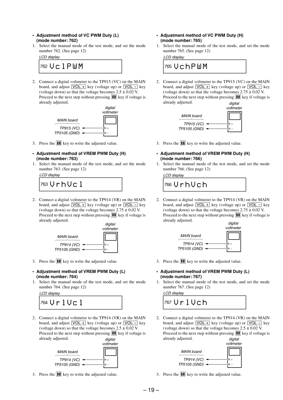
•Adjustment method of VC PWM Duty (L) (mode number: 762)
1.Select the manual mode of the test mode, and set the mode number 762. (See page 12)
LCD display
762V c l P W M
•Adjustment method of VC PWM Duty (H) (mode number: 765)
1.Select the manual mode of the test mode, and set the mode number 765. (See page 12)
LCD display
765V c h P W M
2.Connect a digital voltmeter to the TP915 (VC) on the MAIN board, and adjust [VOL +] key (voltage up) or [VOL
Proceed to the next step without pressing X key if voltage is already adjusted.
digital
voltmeter
MAIN board
TP915 (VC)
TP5105 (GND) ![]()
3. Press the X key to write the adjusted value.
• Adjustment method of VREM PWM Duty (H) (mode number: 763)
1.Select the manual mode of the test mode, and set the mode number 763. (See page 12)
LCD display
763V r h V c l
2.Connect a digital voltmeter to the TP915 (VC) on the MAIN board, and adjust [VOL +] key (voltage up) or [VOL
Proceed to the next step without pressing X key if voltage is
already adjusted.
MAIN board
TP915 (VC)
TP5105 (GND) ![]()
![]()
![]()
3. Press the X key to write the adjusted value.
• Adjustment method of VREM PWM Duty (H) (mode number: 766)
1.Select the manual mode of the test mode, and set the mode number 766. (See page 12)
LCD display
766V r h V c h
2.Connect a digital voltmeter to the TP914 (VR) on the MAIN board, and adjust [VOL +] key (voltage up) or [VOL
Proceed to the next step without pressing X key if voltage is already adjusted.
digital
voltmeter
MAIN board
TP914 (VC)
TP5105 (GND) ![]()
3. Press the X key to write the adjusted value.
•Adjustment method of VREM PWM Duty (L) (mode number: 764)
1.Select the manual mode of the test mode, and set the mode number 764. (See page 12)
LCD display
764V r l V c l
2.Connect a digital voltmeter to the TP914 (VR) on the MAIN board, and adjust [VOL +] key (voltage up) or [VOL
Proceed to the next step without pressing X key if voltage is already adjusted.
digital
voltmeter
MAIN board
TP914 (VC)
TP5105 (GND) ![]()
3. Press the X key to write the adjusted value.
•Adjustment method of VREM PWM Duty (L) (mode number: 767)
1.Select the manual mode of the test mode, and set the mode number 767. (See page 12)
LCD display
767V r l V c h
2.Connect a digital voltmeter to the TP914 (VR) on the MAIN board, and adjust [VOL +] key (voltage up) or [VOL
Proceed to the next step without pressing X key if voltage is
already adjusted.
MAIN board
TP914 (VC)
TP5105 (GND) ![]()
![]()
![]()
3. Press the X key to write the adjusted value.
2.Connect a digital voltmeter to the TP914 (VR) on the MAIN board, and adjust [VOL +] key (voltage up) or [VOL
Proceed to the next step without pressing X key if voltage is
already adjusted.
MAIN board
TP914 (VC)
TP5105 (GND) ![]()
![]()
![]()
3. Press the X key to write the adjusted value.
– 19 –