Model SB1023 | P R E P A R A T I O N | For Machines Mfg. Since 8/09 |
Assembly
After the machine is placed in the final location, and before the lifting apparatus is removed, you should install the machine feet. Included with your machine are four cushioned feet with
To install the feet:
1.Using lifting equipment and wooden blocks, raise and support the machine base so there is approximately 5" between the floor and underside of the base.
2.Remove the jam nuts from the foot studs.
3.Apply any
4.Thread the studs into the machine base from the bottom up until the studs emerge from the cabinet floor approximately 2" (see Figure 7).
Foot Stud
Jam Nut
Threaded
Hole
Machine
Foot ![]()
Figure 7. Machine feet.
5.Thread the jam nuts onto the protruding studs but do not tighten them at this time.
6.Place the machine onto the floor.
7.Using a precision level on the machine table, adjust the feet studs, so the machine is level from
8.Use a 19mm wrench to tighten the jam nuts inside of the cabinet and lock the feet studs into place.
Note: Over the course of the next six months, periodically verify that the machine is still level, and
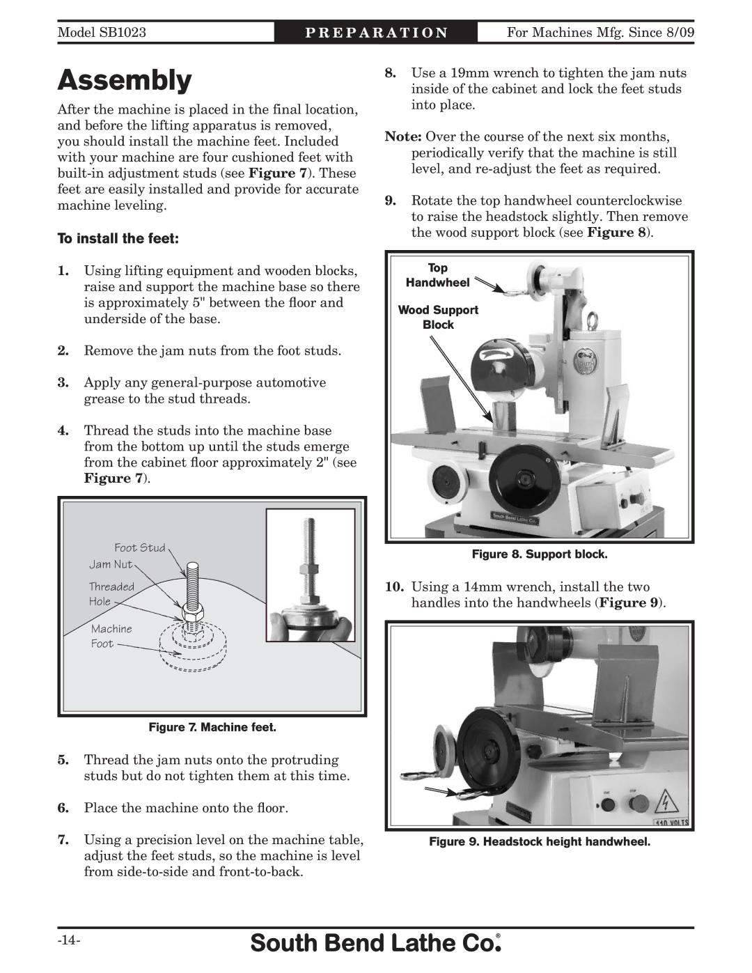
9.Rotate the top handwheel counterclockwise to raise the headstock slightly. Then remove the wood support block (see Figure 8).
Top
Handwheel![]()
![]()
![]()
Wood Support
Block
Figure 8. Support block.
10.Using a 14mm wrench, install the two handles into the handwheels (Figure 9).