SY-7IZB+
7IZB+ Serial
SY-7IZB+
Edition March
Version
Table of Contents
SY-7IZB+ Platform
SY-7IZB+ Motherboard Layout
Introduction
KEY Features
SY-7IZB+ Platform Features
JP9
These processors are not available yet for testing
Handling the Motherboard
Electrostatic Discharge Precautions
Preparations
Hardware Setup
Unpacking the Motherboard
CPU Installation
Installation Guide
CPU Fan Installation
Dimm
Sdram Memory Module Installation
Floppy Drive Installation
IDE Device Installation HDD, CD-ROM
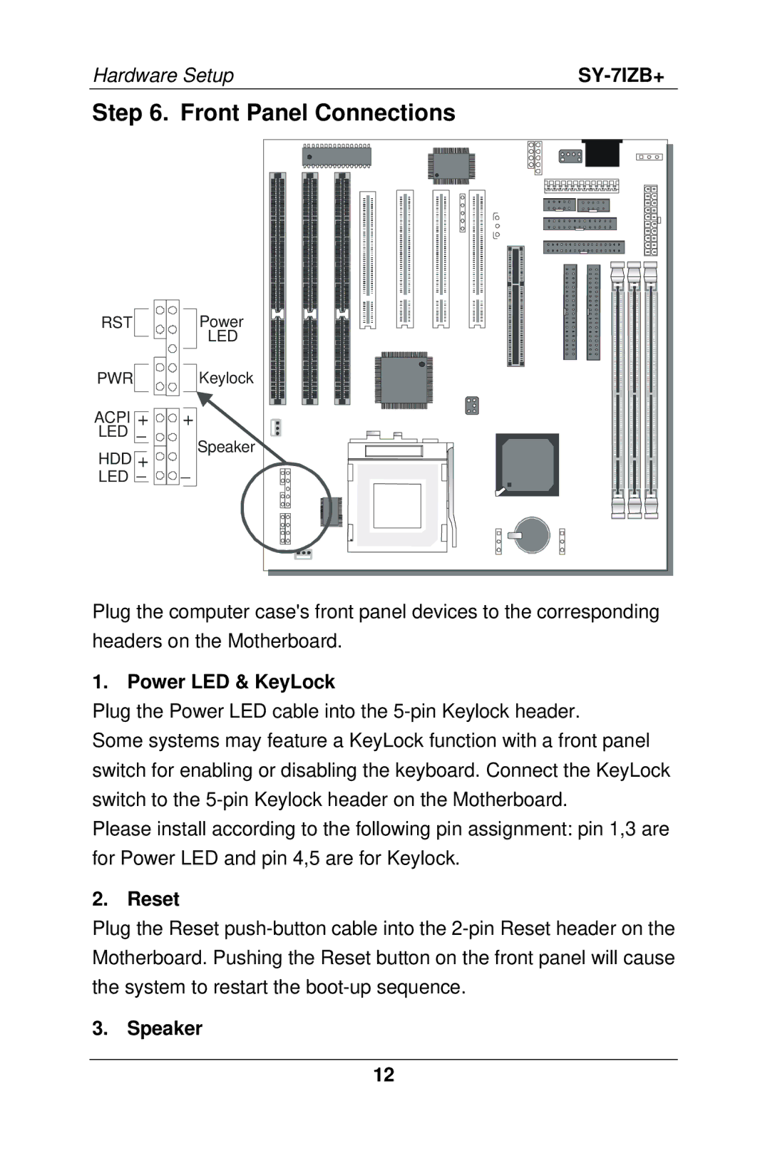
Speaker
Power LED & KeyLock
Reset
Front Panel Connections
ATX Power On/Off Switch
Acpi LED
IDE LED
External Peripherals Connections
Serial Ports COM1/COM2
AT Keyboard
Parallel Port PRT1
Universal Serial Bus USB
PS/2 Mouse
Other Display Cards
Other Connections
Wake-On-LAN WOL
Infrared IR
Cooling Fan Installation
CPU Cooling Fan
Chassis Cooling Fan
ATX Power Supply
AGP VGA Card
PCI Audio Card
GND Ø Pay special care to the directionality
AT Power Supply
JP5
Set JP9 for power up FSB clock and AGP bus clock
Setting
Cmos Clearing JP5
JP10 Setting
Power-On by Keyboard Jumper JP10
Power On
Support Power
Select Load Setup Default
Quick Bios Setup
Select Soyo Combo Setup
Select Standard Cmos Setup
Suspend Mode
Troubleshooting at First Start
Power Off
Select Save & Exit Setup
Modifying selected items
Selecting items
Exit Without Saving
Save and Exit Setup
ROM PCI/ISA Bios Soyo Combo Setup Award SOFTWARE, INC
Soyo Combo Setup
CPU
Power on
PWR-BTTN
Power Management PM Events Power button Setting Description
Power-On by Ring/LAN Power-On by Alarm
HotKey Soft-Off by
CPUFAN2 Speed Vcore, VTT, 3.3V, +12V, -5V, +5V, -12V,VBAT
Current CPU Temperature
Current
CPUFAN1
Standard Cmos Setup
Date & Time Display Setting Please Note
Time
Mode
Hard Disks Type & Mode
Primary Setting Description Secondary Master & Slave Type
Floppy Drives Setting Description Drives a & B
Halt On
Video
ROM PCI/ISA Bios Bios Features Setup Award SOFTWARE, INC
Bios Features Setup
Cache Memory Options Setting Description CPU Internal Cache
Boot Up NumLock Status
External Cache
OS Select for DRAM64MB
Security Option SettingDescription
Typematic Settings Typematic Rate Setting Description
Security Option
Choose how long after Default
Choose the rate at which Default
When holding down a
Typematic Delay
Familiar with the Chipset
Chipset Features Setup
Features
Chipset Features Setup
Spread Spectrum Modulated
Chipset Features Setup
Chipset Features
Passive Release Delayed Transaction AGP Aperture Size
ROM PCI/ISA Bios Power Management Setup Award SOFTWARE, INC
Power Management Setup
Video Off After Modem Use
Power Management Controls Setting Description Acpi function
PM Control by APM
Video Off Method
Down
Doze Mode
Standby Mode
Suspend Mode HDD Power
Parallel Port
IDE0, IDE1
Floppy Disk
Serial Port
This option sets the Motherboards PCI Slots
PNP/PCI Configuration Setup
PNP/PCI
PNP/PCI Configuration Setup
Assign IRQ For USB PnP OS Installed
Slot 1/2/3/4 Use IRQ no Used MEM base addr
ROM PCI/ISA Bios Cmos Setup Utility Award SOFTWARE, INC
Load Setup Defaults
Integrated Peripherals
ROM PCI/ISA Bios Integrated Pweipherals Award SOFTWARD, INC
On-Chip PCI IDE Primary Secondary
IDE
RxD, TxD Active
Onboard Parallel Ports Setting Description
ECP Mode use
EPP Mode Select Pwron After PWR-Fail
DMA
Supervisor Password
SY-7IZB+
This diagram outlines the password selection procedure
User Password
IDE HDD Auto Detection
ROM PCI/ISA Bios Cmos Setup Utility Award SOFTWARE, INC
Insert the Soyo CD into the CD-ROM drive
Drivers Installation
Install Drivers and Utilities
Driver Installation Menu
Following drivers are available for Windows
Intel Southbridge Drivers
Short description of all available drivers follows
Soyo CD Xpress Utility
Fan speed
Check the Latest Releases
Enter the Soyo CD
Core voltage
Select which driver you want to install and click OK