Hardware Installation |
|
4. AUX-IN (AUXIN1)
This Motherboard provides one
Please install according to the following pin assignment:
AUXIN1
Pin Assigment
1 | 2 | 3 | 4 | ||||
|
|
|
|
|
|
| |
Left |
|
| GND |
| |||
|
|
| Right | ||||
| GND | ||||||
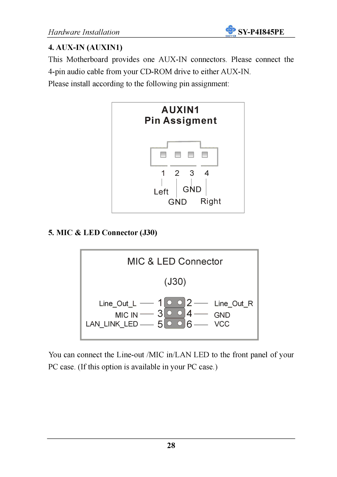
5. MIC & LED Connector (J30)
MIC & LED Connector
Line_Out_L
MIC IN LAN_LINK_LED
(J30)
1![]() 2
2
3 ![]()
![]() 4
4
5![]() 6
6
Line_Out_R
GND
VCC
You can connect the
28