ASSEMBLY INSTRUCTIONS
Place all parts from the box in a cleared area and position them on the floor in front of you. Remove all packing materials from your area and place them back into the box. Do not dispose of the packing materials until assembly is completed. Read each step carefully before beginning. If you are missing a part please call our
parts@staminaproducts.com
LEFT |
|
R | RIGHT |
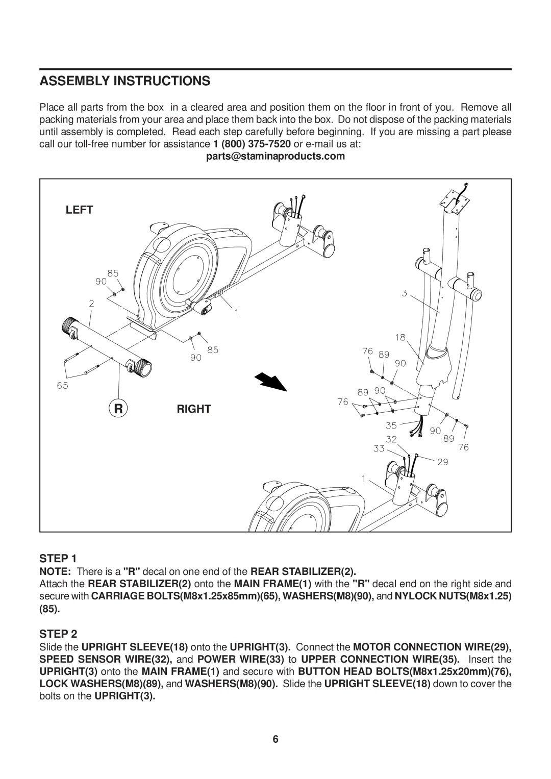
STEP 1
NOTE: There is a "R" decal on one end of the REAR STABILIZER(2).
Attach the REAR STABILIZER(2) onto the MAIN FRAME(1) with the "R" decal end on the right side and secure with CARRIAGE BOLTS(M8x1.25x85mm)(65), WASHERS(M8)(90), and NYLOCK NUTS(M8x1.25) (85).
STEP 2
Slide the UPRIGHT SLEEVE(18) onto the UPRIGHT(3). Connect the MOTOR CONNECTION WIRE(29), SPEED SENSOR WIRE(32), and POWER WIRE(33) to UPPER CONNECTION WIRE(35). Insert the UPRIGHT(3) onto the MAIN FRAME(1) and secure with BUTTON HEAD BOLTS(M8x1.25x20mm)(76), LOCK WASHERS(M8)(89), and WASHERS(M8)(90). Slide the UPRIGHT SLEEVE(18) down to cover the bolts on the UPRIGHT(3).
6