Connectors and Signals | ||||||
|
|
|
|
|
|
|
Pin No. |
| Signal | Direction |
| Function | |
| Name |
| ||||
|
|
|
|
| ||
|
|
|
|
|
|
|
1 |
| GND | — |
| Shield Ground | |
|
|
|
|
|
|
|
2 |
| GND | — |
| Frame Ground | |
|
|
|
|
|
|
|
3 |
| TXD | OUT |
| This pin carries data from the printer. | |
|
| (Return channel) | ||||
|
|
|
|
|
| |
|
|
|
|
|
|
|
4 |
| RXD | IN |
| This pin carries data to the printer. | |
|
|
|
|
|
|
|
5 |
| RTS | OUT |
| This is SPACE when the printer power is ON. | |
|
|
|
|
|
|
|
6 |
|
|
| OUT |
| This is MARK when the printer is abnormal. |
| FAULT |
|
| (Refer to Error Condition Alarm Mode *1.) | ||
|
|
|
|
|
| |
|
|
|
|
|
| Or there is a paper error. |
|
|
|
|
|
| |
7 |
| GND | — |
| Signal ground. | |
|
|
|
|
|
|
|
8 |
| DTR | OUT |
| This printer turns this pin SPACE when | |
|
| it is ready to receive data. | ||||
|
|
|
|
|
| |
|
|
|
|
|
|
|
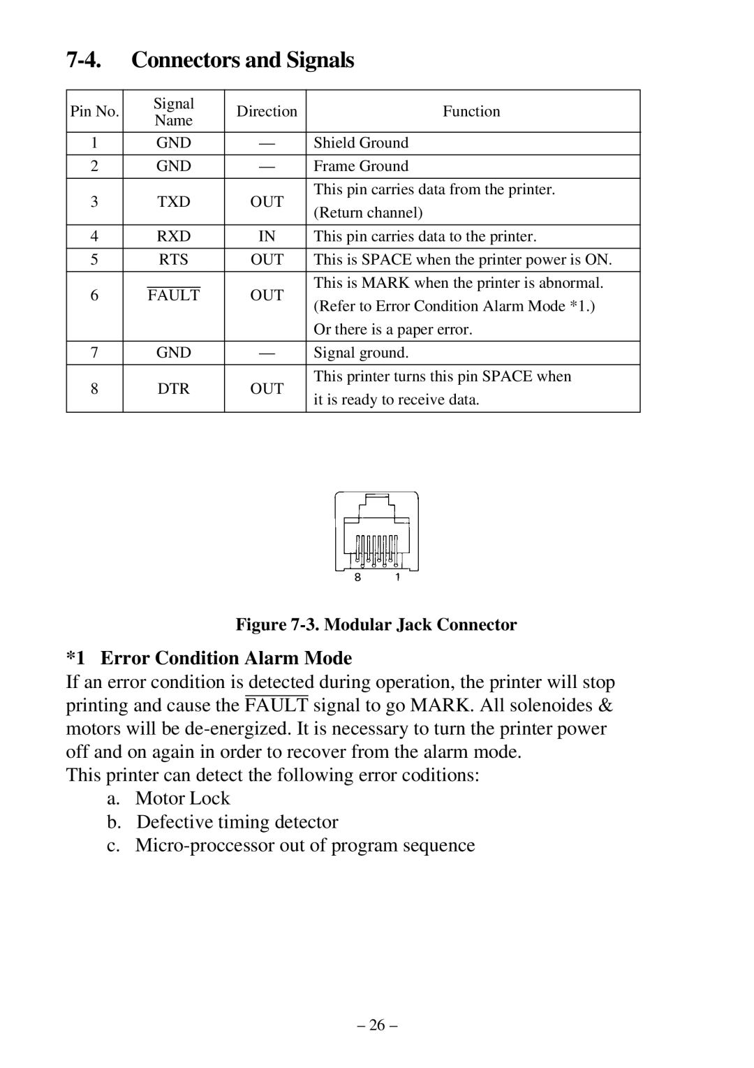
Figure 7-3. Modular Jack Connector
*1 Error Condition Alarm Mode
If an error condition is detected during operation, the printer will stop printing and cause the FAULT signal to go MARK. All solenoides & motors will be
This printer can detect the following error coditions:
a.Motor Lock
b.Defective timing detector
c.
– 26 –