Using a 5 mm hex key, secure the display mounting bracket to the TOTAL BODY
TRAINER neck using four M6 X 70 socket head cap screws with lockwashers. TIGHT-
EN THE SCREWS SECURELY.
Step 2C
Plug the display cable connector into the socket on the display electronics board. Be sure the connector is oriented properly, and is fully seated in the socket.
Step 2D
Position the back cover on the display and secure with six #8 X 1/2”
Step 2E
Using a #2 Phillips screwdriver and one #10 X 1” screw, secure the bottom of the dis- play cover to the display mounting bracket.
Step 3B
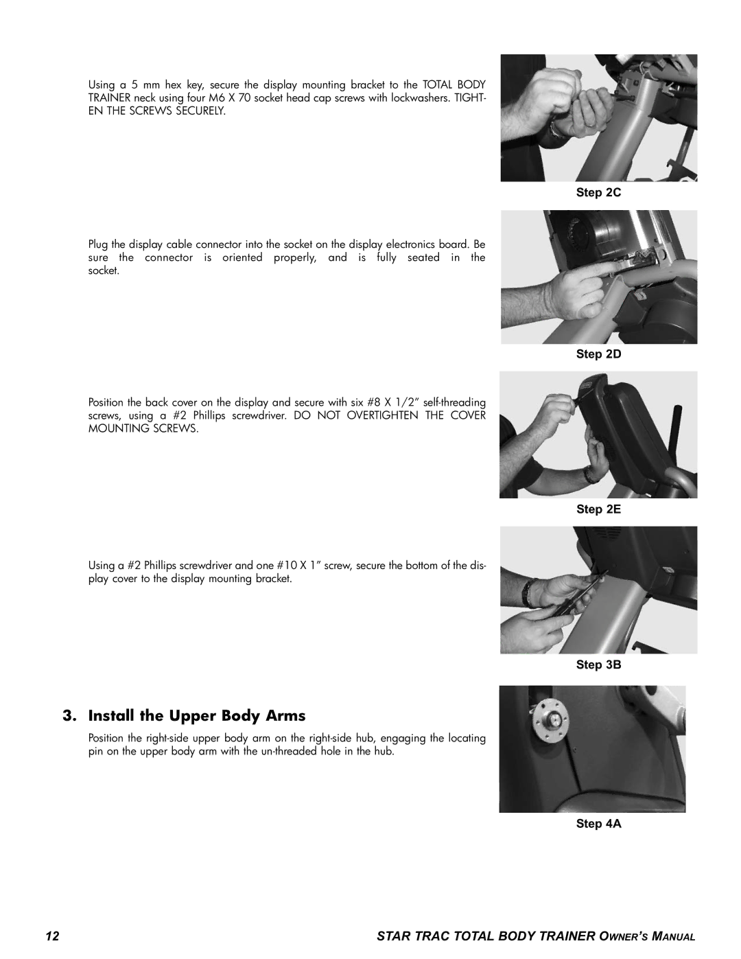
3. Install the Upper Body Arms
Position the
Step 4A
12 | STAR TRAC TOTAL BODY TRAINER OWNER’S MANUAL |