4.Do not plug in power cord until vent system is completely installed. The Power Vent operates on 120 Vac, therefore a grounded outlet must be within reach of the 6 foot flexible power cord supplied with the vent. The power cord supplied may be used on unit only where local codes permit. If local codes do not permit use of flexible power supply cord:

A.Remove screws that hold cover plate on control box and remove plate.

B.Cut flexible power cord on inside of control box, as close to inside wall as possible.

C.If flexible cord and strain relief are removed, then opening in box must be covered by a plastic cap on the front side of the control box.

D.Remove plastic cap on the right side of control box and install suitable conduit fitting in enclosure.

E.Splice field wiring into existing wiring using code authorized method (wire nuts, etc.).

F.Be certain that neutral and line connections are not reversed when making these connections.

G.Ground heater properly. This water heater must be grounded in accordance with the National Electrical Code ANSI/ NFPA70 and/or local codes. These must be followed in all cases.

The water heater must be connected to a grounded metal, permanent wiring system; or an equipment grounding conductor must be run with the circuit conductors and connected to the equipment grounding terminal or lead on the water heater, see Figure 19.

H.Replace cover plate and secure with two screws.

5.The blower discharge boot is made to accept only straight sections of 3” pipe. To start off with an elbow, a short section of the furnished pipe, a minimum of 2 inches, must be cut and glued into the end of the elbow that will mount on the discharge boot (see figure 16).

INSTALLATION OF VENT SYSTEM

Before beginning installation of piping system thoroughly read the section of this manual VENT PIPE PREPARATION.

If you are installing your system so that it vents through the roof, please refer to section titled INSTALLATION OF VERTICAL VENT SYSTEM.

VENT TERMINAL INSTALLATION, SIDEWALL

1.Install the vent terminal by using the cover plate as a template to mark the hole for the vent pipe to pass through the wall. BEWARE OF CONCEALED WIRING AND PIPING INSIDE THE WALL.

2.If the Vent Terminal is being installed on the outside of a finished wall, it may be easier to mark both the inside and outside wall. Align the holes by drilling a hole through the center of the template from the inside through to the outside. The template can now be positioned on the outside wall using the drilled hole as a centering point for the template.

3.A) MASONRY SIDE WALLS

Chisel an opening approximately one half inch (1.3 cm) larger than the marked circle.

B) WOODEN SIDE WALLS

Drill a pilot hole approximately one quarter inch (0.64 cm) outside of the marked circle. This pilot hole is used as a starting point for a saws-all or sabre saw blade. Cut around the marked circle staying approximately one quarter inch (0.64 cm) outside of the line. (This will allow the vent to easily slide through the opening. The resulting gap will be covered up by the Vent Terminal cover plate.) Repeat this step on inside wall if necessary.

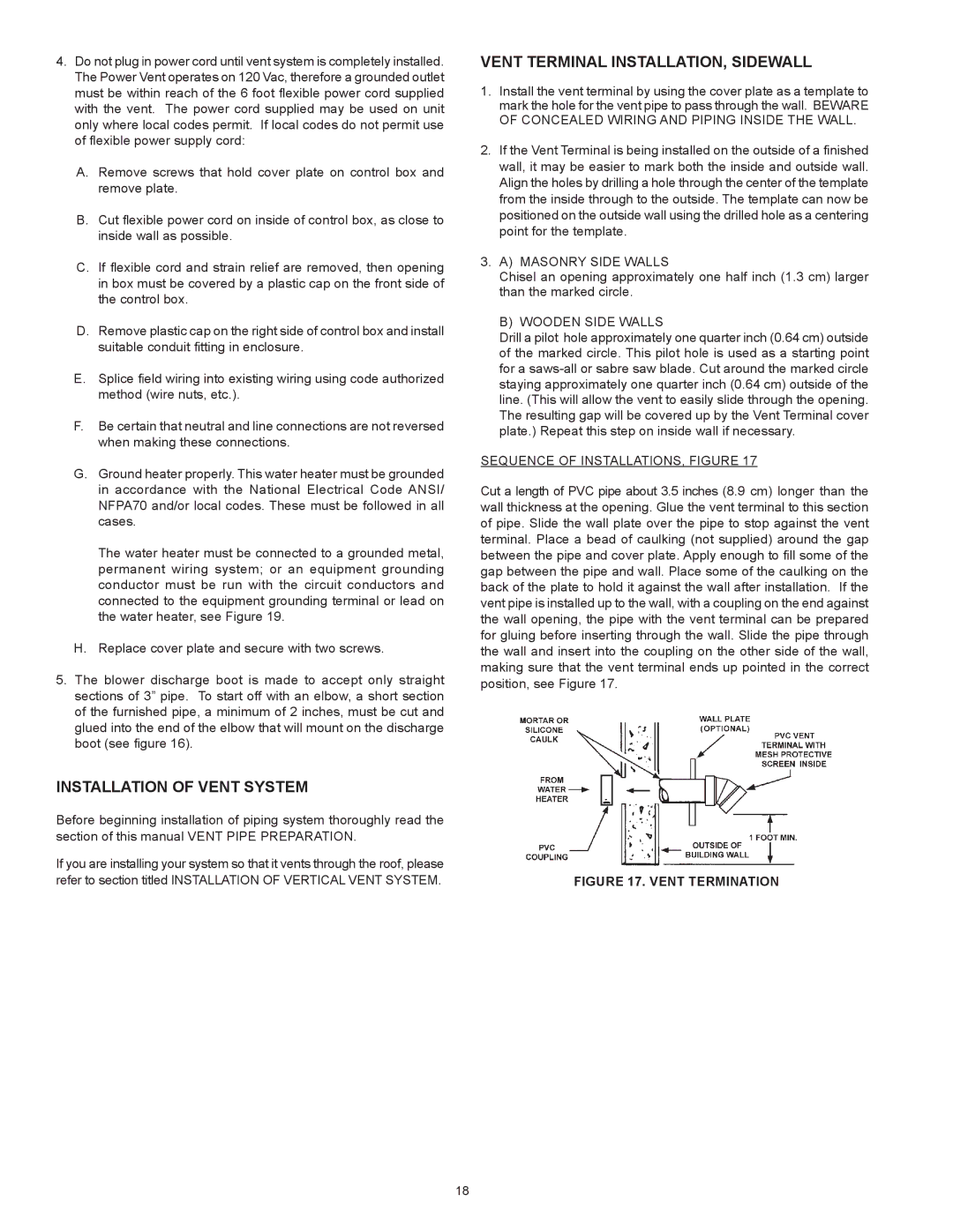
SEQUENCE OF INSTALLATIONS, FIGURE 17

Cut a length of PVC pipe about 3.5 inches (8.9 cm) longer than the wall thickness at the opening. Glue the vent terminal to this section of pipe. Slide the wall plate over the pipe to stop against the vent terminal. Place a bead of caulking (not supplied) around the gap between the pipe and cover plate. Apply enough to fill some of the gap between the pipe and wall. Place some of the caulking on the back of the plate to hold it against the wall after installation. If the vent pipe is installed up to the wall, with a coupling on the end against the wall opening, the pipe with the vent terminal can be prepared for gluing before inserting through the wall. Slide the pipe through the wall and insert into the coupling on the other side of the wall, making sure that the vent terminal ends up pointed in the correct position, see Figure 17.

FIGURE 17. VENT TERMINATION

18

Page 18
Image 18
State Industries GS675YRVIT, GS675HRVIT instruction manual Installation of Vent System, Vent Terminal INSTALLATION, Sidewall

GS675HRVIT, GS675YRVIT specifications

The State Industries GS675HRVIT and GS675YRVIT are high-efficiency water heaters designed to meet the growing demand for reliable and energy-efficient hot water solutions. These models are ideal for both residential and light commercial applications, offering a blend of advanced technology, durable construction, and user-friendly features.

One of the standout characteristics of the GS675HRVIT and GS675YRVIT is their compact design, which makes them easy to install in various spaces without compromising performance. Both units are equipped with a high-efficiency gas burner that provides rapid water heating capabilities. Their power input allows for quick recovery rates, ensuring a steady supply of hot water when needed.

Energy efficiency is a key feature of these models. They utilize advanced insulation materials and designs that minimize heat loss, thus significantly reducing energy consumption. This not only contributes to lower utility bills but also supports environmental sustainability efforts by lowering carbon footprints. Both models are designed to meet or exceed Energy Star certification standards, highlighting their commitment to energy conservation.

In terms of technology, the GS675HRVIT and GS675YRVIT incorporate robust safety features, including a temperature and pressure relief valve that prevents dangerous pressure build-up, as well as an electronic ignition system that improves reliability by eliminating the need for a standing pilot light. Additionally, the gas control valve ensures precise regulation of the water temperature, enhancing safety and comfort for users.

Durability is another hallmark of these water heaters. Constructed with high-quality materials, the units feature a glass-lined tank that resists corrosion, extending the lifecycle of the product. They also come with a comprehensive warranty, providing peace of mind for consumers regarding their investment.

Users will appreciate the convenience that the GS675HRVIT and GS675YRVIT models offer, including easy-to-use controls and clear indicators for operational status. Installation and maintenance are simplified, making it straightforward for both homeowners and professionals to manage the unit over time.

Overall, State Industries GS675HRVIT and GS675YRVIT are excellent choices for anyone looking for efficient, reliable, and durable water heating solutions. With their innovative technology, energy-saving features, and user-friendly design, these models stand out in the competitive market of hot water heaters.