U.S. HORIZONTAL VENT CLEARANCES

WARNING

VENT HOOD(S) MAY BE

EXTREMELY HOT

DURING OPERATION.

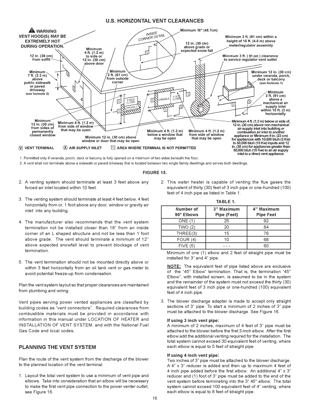
FIGURE 15.

2.A venting system should terminate at least 3 feet above any forced air inlet located within 10 feet.

3.The venting system should terminate at least 4 feet below, 4 feet horizontally from or, 1 foot above any door, window or gravity air inlet into any building.

4.The manufacturer also recommends that the vent system termination not be installed closer than 18” from an inside corner of an L shaped structure and not be less than 1 foot above grade. The vent should terminate a minimum of 12’’ above expected snowfall level to prevent blockage of vent termination.

5.The vent termination should not be mounted directly above or within 3 feet horizontally from an oil tank vent or gas meter to avoid potential freeze-up from condensation.

Plan the vent system layout so that proper clearances are maintained from plumbing and wiring.

Vent pipes serving power vented appliances are classified by building codes as “vent connectors”. Required clearances from combustible materials must be provided in accordance with information in this manual under LOCATION OF HEATER and INSTALLATION OF VENT SYSTEM, and with the National Fuel Gas Code and local codes.

PLANNING THE VENT SYSTEM

Plan the route of the vent system from the discharge of the blower to the planned location of the vent terminal.

1.Layout the total vent system to use a minimum of vent pipe and elbows. Take into consideration that an elbow will be necessary to make the first vent pipe connection to the power venter outlet, see Figure 16.

2.This water heater is capable of venting the flue gases the equivalent of thirty (30) feet of 3 inch pipe or one-hundred (100) feet of 4 inch pipe as listed in Table 1.

TABLE 1.

Number of

3” Maximum

4” Maximum

90° Elbows

Pipe (Feet)

Pipe Feet

ONE (1)

25

92

TWO (2)

20

84

THREE(3)

15

76

FOUR (4)

10

68

FIVE (5)

- - -

60

Minimum of one (1) elbow and 2 feet of straight pipe must be installed for 3” and 4” pipe.

NOTE: The equivalent feet of pipe listed above are exclusive of the “45° Elbow” termination. That is, the termination “45° Elbow”, with installed screen, is assumed to be in the system and the remainder of the system must not exceed the thirty (30) equivalent feet of 3 inch pipe or one-hundred (100) equivalent feet of 4 inch pipe.

3.The blower discharge adapter is made to accept only straight sections of 3” pipe. To start a minimum of 2 inches of 3” pipe must be attached to the blower discharge. See Figure 16.

If using 3 inch vent pipe:

A minimum of 2 inches, maximum of 4 feet of 3” pipe must be attached to the blower before the first 3-inch elbow. After the first elbow add the additional venting required for the installation. The total system cannot exceed 30 equivalent feet of venting, where each elbow is equal to 5 feet of straight pipe.

If using 4 inch vent pipe:

Two inches of 3” pipe must be attached to the blower discharge. A 4” x 3” reducer is added and then up to maximum 4 feet of 4 inch pipe added before the first elbow. An additional 4” x 3” reducer and (1) foot of 3” pipe must be added to the end of the vent system before terminating into the 3” 45° elbow. The total system cannot exceed 100 equivalent feet of 4” venting, where each elbow is equal to 8 feet of straight pipe.

16

Page 16
Image 16
State Industries GS675YRVIT, GS675HRVIT instruction manual Horizontal Vent Clearances, Planning the Vent System

GS675HRVIT, GS675YRVIT specifications

The State Industries GS675HRVIT and GS675YRVIT are high-efficiency water heaters designed to meet the growing demand for reliable and energy-efficient hot water solutions. These models are ideal for both residential and light commercial applications, offering a blend of advanced technology, durable construction, and user-friendly features.

One of the standout characteristics of the GS675HRVIT and GS675YRVIT is their compact design, which makes them easy to install in various spaces without compromising performance. Both units are equipped with a high-efficiency gas burner that provides rapid water heating capabilities. Their power input allows for quick recovery rates, ensuring a steady supply of hot water when needed.

Energy efficiency is a key feature of these models. They utilize advanced insulation materials and designs that minimize heat loss, thus significantly reducing energy consumption. This not only contributes to lower utility bills but also supports environmental sustainability efforts by lowering carbon footprints. Both models are designed to meet or exceed Energy Star certification standards, highlighting their commitment to energy conservation.

In terms of technology, the GS675HRVIT and GS675YRVIT incorporate robust safety features, including a temperature and pressure relief valve that prevents dangerous pressure build-up, as well as an electronic ignition system that improves reliability by eliminating the need for a standing pilot light. Additionally, the gas control valve ensures precise regulation of the water temperature, enhancing safety and comfort for users.

Durability is another hallmark of these water heaters. Constructed with high-quality materials, the units feature a glass-lined tank that resists corrosion, extending the lifecycle of the product. They also come with a comprehensive warranty, providing peace of mind for consumers regarding their investment.

Users will appreciate the convenience that the GS675HRVIT and GS675YRVIT models offer, including easy-to-use controls and clear indicators for operational status. Installation and maintenance are simplified, making it straightforward for both homeowners and professionals to manage the unit over time.

Overall, State Industries GS675HRVIT and GS675YRVIT are excellent choices for anyone looking for efficient, reliable, and durable water heating solutions. With their innovative technology, energy-saving features, and user-friendly design, these models stand out in the competitive market of hot water heaters.