STANDARD COMBUSTION
VERTICALLY VENTED, CATEGORY III – Figure 17 & 19
Observe the following precautions when venting the unit:
1.Use flue pipe of the same size as the flue connection(s) on the gas unit heater, 4" (102mm). All heaters must be vented with a single or double wall pipe listed for positive pressure vent systems.
2.Each unit must have an individual vent pipe and vent terminal. Unit MUST NOT be connected to other vent systems or to a chimney.
3.Category III units are limited to a maximum of 40 feet (12.19m) equivalent length of vent pipe. Equivalent length is the total length of straight sections PLUS 5 feet (1.5m) for each 90 degree elbow and 2.5 feet (.75m) for each 45 degree elbow.
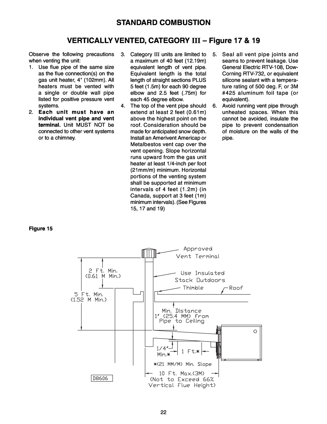
4.The top of the vent pipe should extend at least 2 feet (0.61m) above the highest point on the roof. Consideration should be made for anticipated snow depth. Install an Amerivent Americap or Metalbestos vent cap over the vent opening. Slope horizontal runs upward from the gas unit heater at least
5.Seal all vent pipe joints and seams to prevent leakage. Use General Electric
6.Avoid running vent pipe through unheated spaces. When this cannot be avoided, insulate the pipe to prevent condensation of moisture on the walls of the pipe.
Figure 15
22