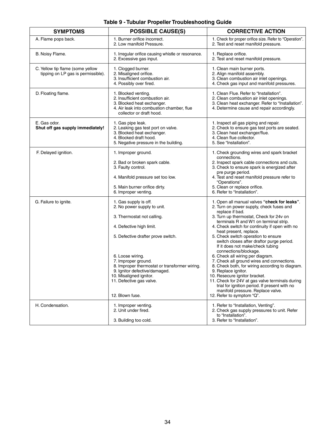
Table 9 - Tubular Propeller Troubleshooting Guide
SYMPTOMS | POSSIBLE CAUSE(S) | CORRECTIVE ACTION |
|
|
|
A. Flame pops back. | 1. Burner orifice incorrect. | 1. Check for proper orifice size. Refer to “Operation”. |
| 2. Low manifold Pressure. | 2. Test and reset manifold pressure. |
|
|
|
B. Noisy Flame. | 1. Irregular orifice causing whistle or resonance. | 1. Replace orifice. |
| 2. Excessive gas input. | 2. Test and reset manifold pressure. |
|
|
|
C. Yellow tip flame (some yellow | 1. Clogged burner. | 1. Clean main burner ports. |
tipping on LP gas is permissible). | 2. Misaligned orifice. | 2. Align manifold assembly. |
| 3. Insufficient combustion air. | 3. Clean combustion air inlet openings. |
| 4. Possibly over fired. | 4. Check gas input and manifold pressures. |
|
|
|
D. Floating flame. | 1. Blocked venting. | 1. Clean Flue. Refer to “Installation”. |
| 2. Insufficient combustion air. | 2. Clean combustion air inlet openings. |
| 3. Blocked heat exchanger. | 3. Clean heat exchanger. Refer to “Installation”. |
| 4. Air leak into combustion chamber, flue | 4. Determine cause and repair accordingly. |
| collector or draft hood. |
|
|
|
|
E. Gas odor. | 1. Gas pipe leak. | 1. Inspect all gas piping and repair. |
Shut off gas supply immediately! | 2. Leaking gas test port on valve. | 2. Check to ensure gas test ports are seated. |
| 3. Blocked heat exchanger. | 3. Clean heat exchanger/flue. |
| 4. Blocked draft hood. | 4. Clean flue collector. |
| 5. Negative pressure in the building. | 5. See “Installation”. |
|
|
|
F. Delayed ignition. | 1. Improper ground. | 1. Check grounding wires and spark bracket |
|
| connections. |
| 2. Bad or broken spark cable. | 2. Inspect spark cable connections and cuts. |
| 3. Faulty control. | 3. Check to ensure spark is energized after |
|
| pre purge period. |
| 4. Manifold pressure set too low. | 4. Test and reset manifold pressure refer to |
|
| “Operations”. |
| 5. Main burner orifice dirty. | 5. Clean or replace orifice. |
| 6. Improper venting. | 6. Refer to “Installation”. |
|
|
|
G. Failure to ignite. | 1. Gas supply is off. | 1. Open all manual valves “check for leaks”. |
| 2. No power supply to unit. | 2. Turn on power supply, check fuses and |
|
| replace if bad. |
| 3. Thermostat not calling. | 3. Turn up thermostat, Check for 24v on |
|
| terminals R and W1 on terminal strip. |
| 4. Defective high limit. | 4. Check switch for continuity if open with no |
|
| heat present, replace. |
| 5. Defective drafter prove switch. | 5. Check switch operation to ensure |
|
| switch closes after draftor purge period. |
|
| If it does not make/check tubing |
|
| connections/blockage. |
| 6. Loose wiring. | 6. Check all wiring per diagram. |
| 7. Improper ground. | 7. Check all ground wires and connections. |
| 8. Improper thermostat or transformer wiring. | 8. Check both, for wiring according to diagram. |
| 9. Ignitor defective/damaged. | 9. Replace ignitor. |
| 10. Misaligned ignitor. | 10. Resecure ignitor bracket. |
| 11. Defective gas valve. | 11. Check for 24V at gas valve terminals during |
|
| trial for ignition period. If present with no |
|
| manifold pressure. Replace valve. |
| 12. Blown fuse. | 12. Refer to symptom “Q”. |
|
|
|
H. Condensation. | 1. Improper venting. | 1. Refer to “Installation, Venting”. |
| 2. Unit under fired. | 2. Check gas supply pressures to unit. Refer |
|
| to “Installation”. |
| 3. Building too cold. | 3. Refer to “Installation”. |
|
|
|
34
