HORIZONTALLY VENTED UNIT HEATERS
(CATEGORY III)
All venting of residential tubular unit heaters must comply with the latest edition of CSA .10.96 (2nd ed.) requirement.
Category III horizontal venting arrangements are designed to use single wall vent pipe. These arrange- ments must terminate external to the building using either single wall or double wall (Type B) vent. See Figures 15, 16, and 18 for installa- tion requirements regarding these venting conditions. If double wall venting is used, components that are UL Listed and approved for Category III positive pressure venting systems must be used with one exception: a single 5 foot (1.52 M) section of 4 inch (102mm) Type B vent pipe with a draft hood connector may be used between the appliance vent connection and the vent terminal. Use Metalbestos Type B Gas Vent with a Metalbestos
An Amerivent Americap, Fields Starcap, or Metalbestos vent cap must be supplied by the customer for each power vented unit. The vent pipe diameter MUST be 4 inches (102mm).
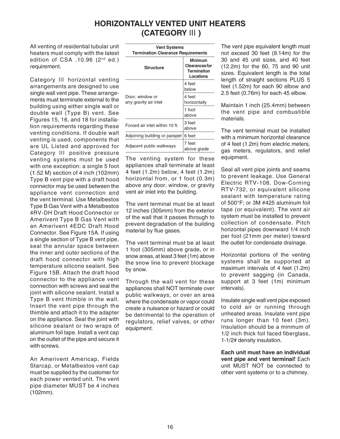
Vent Systems
Termination Clearance Requirements
|
| Minimum | |
Structure | Clearances for | ||
Termination | |||
|
| ||
|
| Locations | |
|
|
| |
|
| 4 feet | |
|
| below | |
|
|
| |
Door, window or | 4 feet | ||
any gravity air inlet | horizontally | ||
|
|
| |
|
| 1 foot | |
|
| above | |
|
|
| |
Forced air inlet within 10 ft. | 3 feet | ||
above | |||
|
| ||
|
| ||
Adjoining building or parapet | 6 feet | ||
|
|
| |
Adjacent public walkways | 7 feet | ||
above grade | |||
|
| ||
|
|
| |
The venting system for these appliances shall terminate at least 4 feet (1.2m) below, 4 feet (1.2m) horizontal from, or 1 foot (0.3m) above any door, window, or gravity vent air inlet into the building.
The vent terminal must be at least 12 inches (305mm) from the exterior of the wall that it passes through to prevent degradation of the building material by flue gases.
The vent terminal must be at least 1 foot (305mm) above grade, or in snow areas, at least 3 feet (1m) above the snow line to prevent blockage by snow.
Through the wall vent for these appliances shall NOT terminate over public walkways, or over an area where the condensate or vapor could create a nuisance or hazard or could be detrimental to the operation of regulators, relief valves, or other equipment.
The vent pipe equivalent length must not exceed 30 feet (9.14m) for the 30 and 45 unit sizes, and 40 feet (12.2m) for the 60, 75 and 90 unit sizes. Equivalent length is the total length of straight sections PLUS 5 feet (1.52m) for each 90 elbow and 2.5 feet (0.76m) for each 45 elbow.
Maintain 1 inch (25.4mm) between the vent pipe and combustible materials.
The vent terminal must be installed with a minimum horizontal clearance of 4 feet (1.2m) from electric meters, gas meters, regulators, and relief equipment.
Seal all vent pipe joints and seams to prevent leakage. Use General Electric
Horizontal portions of the venting systems shall be supported at maximum intervals of 4 feet (1.2m) to prevent sagging (in Canada, support at 3 feet (1m) minimum intervals).
Insulate single wall vent pipe exposed to cold air or running through unheated areas. Insulate vent pipe runs longer than 10 feet (3m). Insulation should be a minmum of 1/2 inch thick foil faced fiberglass,
Each unit must have an individual vent pipe and vent terminal! Each unit MUST NOT be connected to other vent systems or to a chimney.
16