ELECTRICAL CONNECTIONS
HAZARDOUS VOLTAGE! DISCONNECT ALL ELECTRIC POWER INCLUDING REMOTE DISCONNECTS BEFORE SERVICING. Failure to disconnect power before servicing can cause severe personal injury or death.
Standard units are shipped for use on 115 volt, 60 hertz, single phase electric power. The motor
![]()
![]()
![]()
![]()
![]()
![]()
![]() Do not use any tools (i.e. screwdriver, pliers, etc.) across terminals to check for power. Use a voltmeter.
Do not use any tools (i.e. screwdriver, pliers, etc.) across terminals to check for power. Use a voltmeter.
It is recommended that the electrical power supply to each unit heater be provided by a separate, fused, and permanently live electrical circuit. A disconnect switch of suitable electrical rating should be located as close to the gas valve and controls as possible. Each unit heater must be electrically grounded in accordance with the latest edition of the National Electrical Code, ANSI/NFPA No. 70, or CSA Standard C22.1. Refer to Figures 7, 8 and 9.
Figure 7 - Low-voltage Thermostat Wiring Single Stage
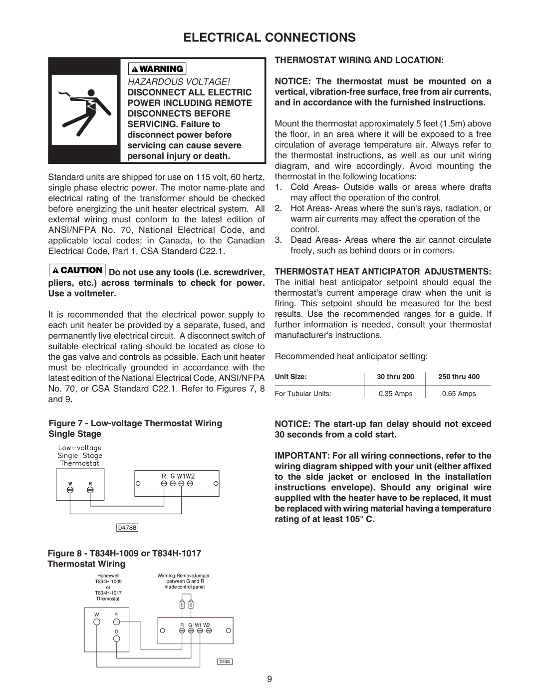
Figure 8 - T834H-1009 or T834H-1017
Thermostat Wiring
Honeywell | Warning: RemoveJumper | |
between G and R | ||
| or | inside control panel |
| ||
Thermostat |
| |
W | R |
|
|
| R G W1 W2 |
| G |
|
THERMOSTAT WIRING AND LOCATION:
NOTICE: The thermostat must be mounted on a vertical,
Mount the thermostat approximately 5 feet (1.5m) above the floor, in an area where it will be exposed to a free circulation of average temperature air. Always refer to the thermostat instructions, as well as our unit wiring diagram, and wire accordingly. Avoid mounting the thermostat in the following locations:
1.Cold Areas- Outside walls or areas where drafts may affect the operation of the control.
2.Hot Areas- Areas where the sun's rays, radiation, or warm air currents may affect the operation of the control.
3.Dead Areas- Areas where the air cannot circulate freely, such as behind doors or in corners.
THERMOSTAT HEAT ANTICIPATOR ADJUSTMENTS: The initial heat anticipator setpoint should equal the thermostat's current amperage draw when the unit is firing. This setpoint should be measured for the best results. Use the recommended ranges for a guide. If further information is needed, consult your thermostat manufacturer's instructions.
Recommended heat anticipator setting:
Unit Size: | 30 thru 200 | 250 thru 400 |
|
|
|
For Tubular Units: | 0.35 Amps | 0.65 Amps |
NOTICE: The
IMPORTANT: For all wiring connections, refer to the wiring diagram shipped with your unit (either affixed to the side jacket or enclosed in the installation instructions envelope). Should any original wire supplied with the heater have to be replaced, it must be replaced with wiring material having a temperature rating of at least 105° C.
D6922
9