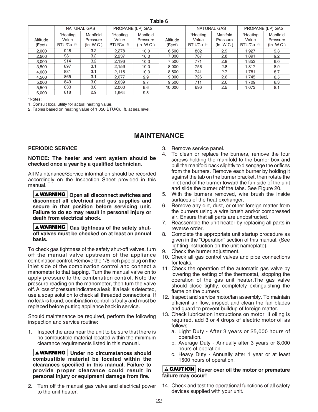
Table 6
| NATURAL GAS | PROPANE (LP) GAS |
| NATURAL GAS | PROPANE (LP) GAS | ||||
| *Heating | Manifold | *Heating | Manifold |
| *Heating | Manifold | *Heating | Manifold |
Altitude | Value | Pressure | Value | Pressure | Altitude | Value | Pressure | Value | Pressure |
(Feet) | BTU/Cu. ft. | (In. W.C.) | BTU/Cu. ft. | (In. W.C.) | (Feet) | BTU/Cu. ft. | (In. W.C.) | BTU/Cu. ft. | (In. W.C.) |
|
|
|
|
|
|
|
|
|
|
2,000 | 948 | 3.2 | 2,278 | 10.0 | 6,500 | 802 | 2.9 | 1,927 | 9.3 |
2,500 | 931 | 3.2 | 2,237 | 10.0 | 7,000 | 787 | 2.8 | 1,891 | 9.2 |
3,000 | 914 | 3.2 | 2,196 | 10.0 | 7,500 | 771 | 2.8 | 1,853 | 9.0 |
3,500 | 897 | 3.1 | 2,156 | 10.0 | 8,000 | 756 | 2.8 | 1,817 | 8.9 |
4,000 | 881 | 3.1 | 2,116 | 10.0 | 8,500 | 741 | 2.7 | 1,781 | 8.7 |
4,500 | 865 | 3.1 | 2,077 | 9.9 | 9,000 | 726 | 2.6 | 1,745 | 8.5 |
5,000 | 849 | 3.0 | 2,039 | 9.7 | 9,500 | 711 | 2.6 | 1,709 | 8.3 |
5,500 | 833 | 3.0 | 2,000 | 9.6 | 10,000 | 696 | 2.5 | 1,673 | 8.1 |
6,000 | 818 | 2.9 | 1,964 | 9.5 |
|
|
|
|
|
*Notes:
1.Consult local utility for actual heating value.
2.Tables based on heating value of 1,050 BTU/Cu. ft. at sea level.
MAINTENANCE
PERIODIC SERVICE
NOTICE: The heater and vent system should be checked once a year by a qualified technician.
All Maintenance/Service information should be recorded accordingly on the Inspection Sheet provided in this manual.
![]()
![]()
![]()
![]()
![]()
![]()
![]() Open all disconnect switches and disconnect all electrical and gas supplies and secure in that position before servicing unit. Failure to do so may result in personal injury or death from electrical shock.
Open all disconnect switches and disconnect all electrical and gas supplies and secure in that position before servicing unit. Failure to do so may result in personal injury or death from electrical shock.
![]()
![]()
![]()
![]()
![]()
![]()
![]() Gas tightness of the safety shut- off valves must be checked on at least an annual basis.
Gas tightness of the safety shut- off valves must be checked on at least an annual basis.
To check gas tightness of the safety
Should maintenance be required, perform the following inspection and service routine:
1.Inspect the area near the unit to be sure that there is no combustible material located within the minimum clearance requirements listed in this manual.
![]()
![]()
![]()
![]()
![]()
![]()
![]() Under no circumstances should combustible material be located within the clearances specified in this manual. Failure to provide proper clearance could result in personal injury or equipment damage from fire.
Under no circumstances should combustible material be located within the clearances specified in this manual. Failure to provide proper clearance could result in personal injury or equipment damage from fire.
2.Turn off the manual gas valve and electrical power to the unit heater.
3.Remove service panel.
4.To clean or replace the burners, remove the four screws holding the manifold to the burner box and pull the manifold back slightly to disengage the orifices from the burners. Remove each burner by holding it against the tab on the burner bracket, then rotate the inlet end of the burner toward the fan side of the unit and slide the burner off the tabs. See Figure 20.
5.With the burners removed, wire brush the inside surfaces of the heat exchanger.
6.Remove any dirt, dust, or other foreign matter from the burners using a wire brush and/or compressed air. Ensure that all parts are unobstructed.
7.Reassemble the unit heater by replacing all parts in reverse order.
8.Complete the appropriate unit startup procedure as given in the “Operation” section of this manual. (See lighting instruction on the unit nameplate).
9.Check the burner adjustment.
10.Check all gas control valves and pipe connections for leaks.
11Check the operation of the automatic gas valve by lowering the setting of the thermostat, stopping the operation of the gas unit heater.The gas valve
should close tightly, completely extinguishing the flame on the burners.
12.Inspect and service motor/fan assembly. To maintain efficient air flow, inspect and clean the fan blades and guard to prevent buildup of foreign matter.
13.Check lubrication instructions on motor. If oiling is required, add 3 or 4 drops of electric motor oil as follows:
a.Light Duty - After 3 years or 25,000 hours of operation.
b.Average Duty - Annually after 3 years or 8,000 hours of operation.
c.Heavy Duty - Annually after 1 year or at least 1500 hours of operation.


 Never over oil the motor or premature failure may occur!
14.Check and test the operational functions of all safety devices supplied with your unit.
22