4 | Introduction |
Receiving Frame Front Panel
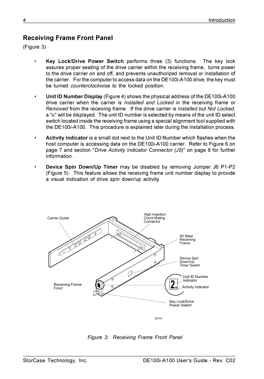
(Figure 3)
•Key Lock/Drive Power Switch performs three (3) functions. The key lock assures proper seating of the drive carrier within the receiving frame, turns power to the drive carrier on and off, and prevents unauthorized removal or installation of the carrier. For the computer to access data on the
•Unit ID Number Display (Figure 4) shows the physical address of the
•Activity Indicator is a small dot next to the Unit ID Number which flashes when the host computer is accessing data on the
•Device Spin Down/Up Timer may be disabled by removing Jumper J6
High Insertion
Carrier GuideCount Mating
Connector
Receiving Frame
Front
All Steel
Receiving
Frame
Device Spin
Down/Up
Timer Switch
Unit ID Number
2. Indicator
Activity Indicator
Key Lock/Drive
Power Switch
0231A
Figure 3: Receiving Frame Front Panel
StorCase Technology, Inc. |