Installation | 7 |
|
|
INSTALLATION
Installing the Drive into the Carrier
NOTE: A #2 Phillips screwdriver will be required during this procedure.
While performing the steps in this section, work on a soft surface to prevent excessive shock to the drive being installed. Also refer to the manufacturer's documentation provided with the
drive.
1.Remove the drive from its protective packaging.
2.Plastic Drive Bezel: If the drive came equipped with a plastic front bezel, it must be removed before installing the drive into the drive carrier.
3.Master/Slave Drive Selection: In most cases, the drive will be
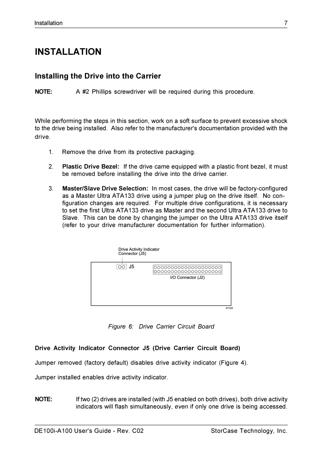
Figure 6: Drive Carrier Circuit Board
Drive Activity Indicator Connector J5 (Drive Carrier Circuit Board)
Jumper removed (factory default) disables drive activity indicator (Figure 4).
Jumper installed enables drive activity indicator.
NOTE: If two (2) drives are installed (with J5 enabled on both drives), both drive activity indicators will flash simultaneously, even if only one drive is being accessed.
StorCase Technology, Inc. |