Introduction | 5 |
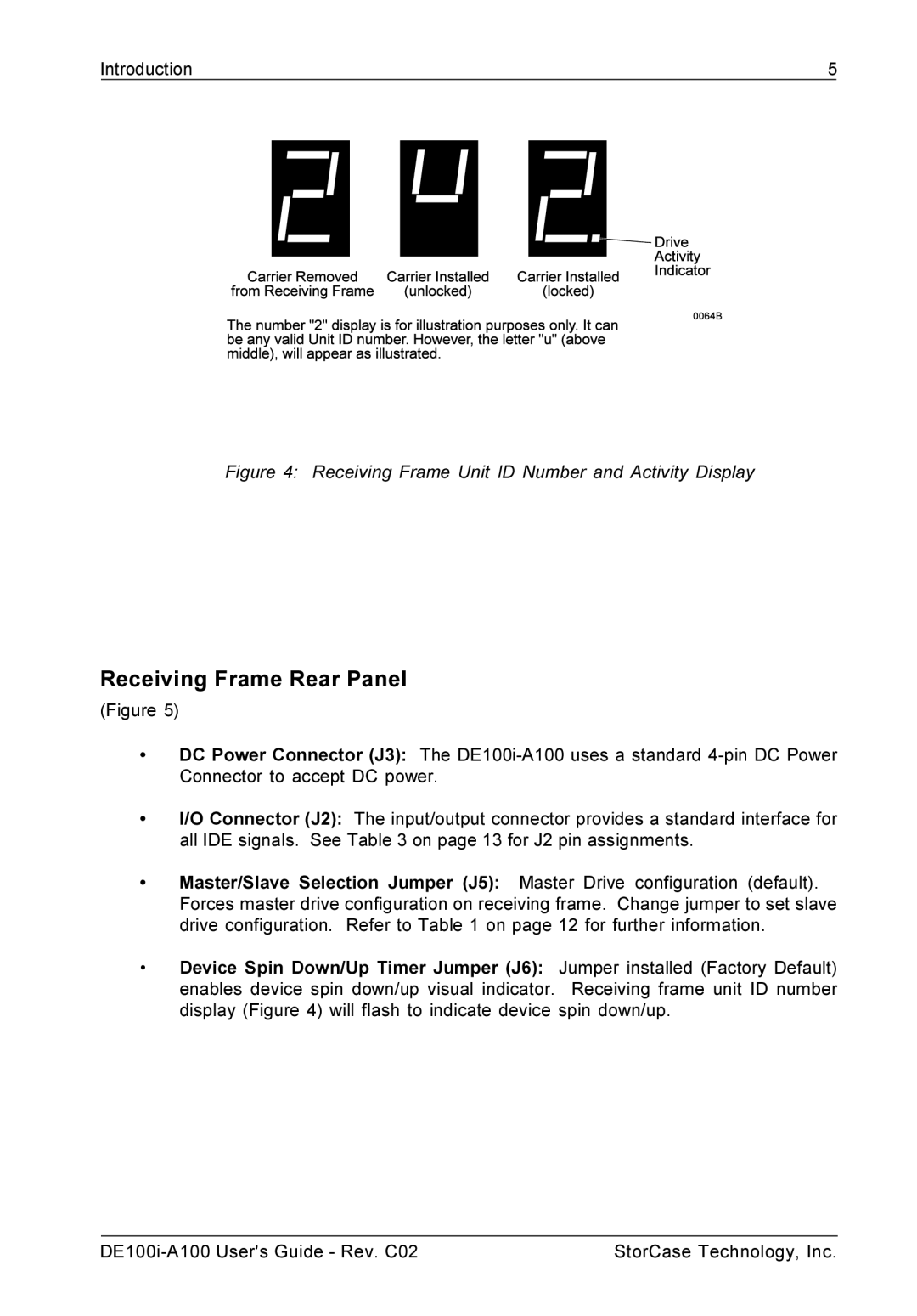
Figure 4: Receiving Frame Unit ID Number and Activity Display
Receiving Frame Rear Panel
(Figure 5)
•DC Power Connector (J3): The
•I/O Connector (J2): The input/output connector provides a standard interface for all IDE signals. See Table 3 on page 13 for J2 pin assignments.
•Master/Slave Selection Jumper (J5): Master Drive configuration (default). Forces master drive configuration on receiving frame. Change jumper to set slave drive configuration. Refer to Table 1 on page 12 for further information.
•Device Spin Down/Up Timer Jumper (J6): Jumper installed (Factory Default) enables device spin down/up visual indicator. Receiving frame unit ID number display (Figure 4) will flash to indicate device spin down/up.
StorCase Technology, Inc. |