SERVICING INSTRUCTIONS
REPLACING PARTS
7.MAIN INJECTOR
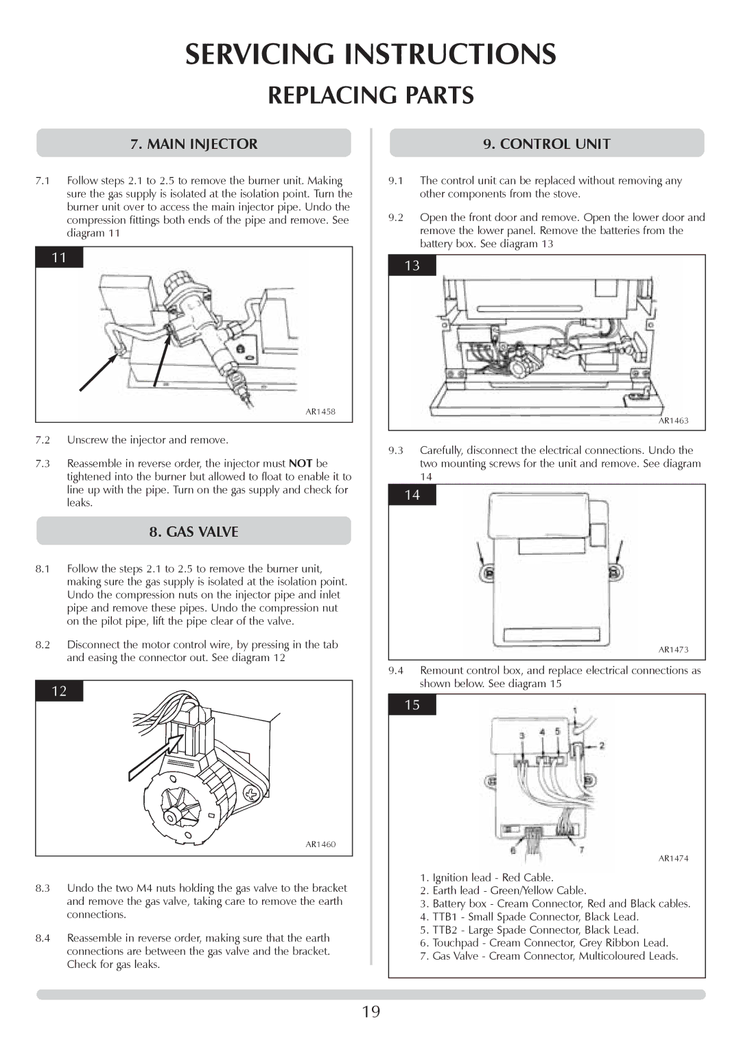
7.1Follow steps 2.1 to 2.5 to remove the burner unit. Making sure the gas supply is isolated at the isolation point. Turn the burner unit over to access the main injector pipe. Undo the compression fittings both ends of the pipe and remove. See diagram 11
11
AR1458
7.2Unscrew the injector and remove.
7.3Reassemble in reverse order, the injector must NOT be tightened into the burner but allowed to float to enable it to line up with the pipe. Turn on the gas supply and check for leaks.
8.GAS VALVE
8.1Follow the steps 2.1 to 2.5 to remove the burner unit, making sure the gas supply is isolated at the isolation point. Undo the compression nuts on the injector pipe and inlet pipe and remove these pipes. Undo the compression nut on the pilot pipe, lift the pipe clear of the valve.
8.2Disconnect the motor control wire, by pressing in the tab and easing the connector out. See diagram 12
12
AR1460
8.3Undo the two M4 nuts holding the gas valve to the bracket and remove the gas valve, taking care to remove the earth connections.
8.4Reassemble in reverse order, making sure that the earth connections are between the gas valve and the bracket. Check for gas leaks.
9.CONTROL UNIT
9.1The control unit can be replaced without removing any other components from the stove.
9.2Open the front door and remove. Open the lower door and remove the lower panel. Remove the batteries from the battery box. See diagram 13
13
AR1463
9.3Carefully, disconnect the electrical connections. Undo the two mounting screws for the unit and remove. See diagram 14
14
AR1473
9.4Remount control box, and replace electrical connections as shown below. See diagram 15
15
AR1474
1.Ignition lead - Red Cable.
2.Earth lead - Green/Yellow Cable.
3.Battery box - Cream Connector, Red and Black cables.
4.TTB1 - Small Spade Connector, Black Lead.
5.TTB2 - Large Spade Connector, Black Lead.
6.Touchpad - Cream Connector, Grey Ribbon Lead.
7.Gas Valve - Cream Connector, Multicoloured Leads.
19
