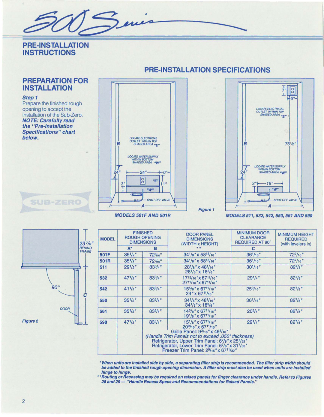
550, 542, 561, 532, 511 specifications
Sub-Zero, a renowned name in luxury refrigeration, has long set the standard for high-performance refrigeration with its exceptional line of products, including models 590, 511, 532, 561, and 542. Each of these models showcases advanced features and cutting-edge technology designed to preserve food freshness while enhancing kitchen aesthetics.The Sub-Zero 590 is a standout model known for its dual refrigeration system, which employs separate systems for the refrigerator and freezer compartments. This innovative approach allows for optimal humidity control and temperature management, preventing cross-contamination of odors and ensuring that perishables remain fresh for longer. Additionally, the 590 boasts a sleek design that can be seamlessly integrated into any kitchen decor.
Model 511 is designed with convenience in mind. Its compact design makes it an excellent choice for smaller kitchens or bar areas. This model continues the tradition of Sub-Zero's high standards, featuring advanced cooling technologies and smart storage solutions, such as adjustable shelving and door storage, maximizing usable space without compromising on performance.
The Sub-Zero 532 elevates the refrigeration experience with its advanced air purification system, which filters out particles and ethylene gas, a natural compound that accelerates ripening in fruits and vegetables. This ensures that your food stays fresher, longer, while preserving its nutritional quality. The model also includes features such as tempered glass shelves and LED lighting, providing both functionality and elegance.
The 561 model impresses with its built-in design, allowing for perfect integration into cabinetry for a custom look. This model offers a generous capacity while maintaining a sleek exterior. Furthermore, it includes advanced technology like a microprocessor control panel that monitors and adjusts temperatures, ensuring that your food is stored under ideal conditions.
Lastly, the Sub-Zero 542 showcases a classic built-in refrigerator/freezer configuration. Its signature design includes the option for a panel-ready finish, allowing homeowners to match it to their cabinetry. With features like smart touch controls and an advanced cooling system that maintains consistent temperatures, the 542 guarantees reliability and performance.
These Sub-Zero models represent the pinnacle of refrigeration technology, with features that prioritize freshness, convenience, and luxury aesthetics, making them a perfect addition to any modern kitchen.

