with its own surround decoder. You can select this as an input from the front panel or remote control. The eight channels of analog audio will then pass into the
Note: if you use
10. Digital Connections
There are four S/PDIF digital coaxial inputs, with one coaxial output, and four digital optical inputs with one optical output.
Use these with source equipment that has digital audio connections.
11. TP1 and TP2
12. RS-232 Port
This communications port allows future updates of the software from Sunfi re to be made to your
13. VIA!migo Port
This port allows connection of a proprietary VIA!migo iPod dock- ing station system available from Sunfi re.
Do not connect this port to Ethernet or other computer networks.
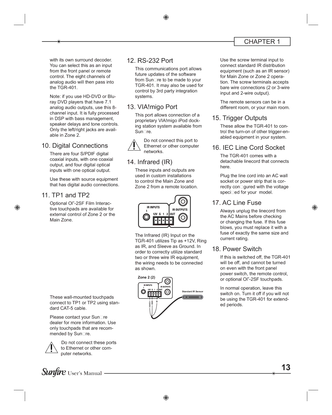
14. Infrared (IR)
These inputs and outputs are used in custom installations to control the Main Zone and Zone 2 from a remote location.
CHAPTER 1
Use the screw terminal input to connect standard IR distribution equipment (such as an IR sensor) for Main Zone or Zone 2 opera- tion. The screw terminals accepts bare wire connections (2 or
The remote sensors can be in a different room, or your main room.
15. Trigger Outputs
These allow the
16. IEC Line Cord Socket
The
Plug the line cord into an AC wall socket or power strip that is cor- rectly confi gured with the voltage specifi ed for your model.
Optional
These
Please contact your Sunfi re dealer for more information. Use only touchpads that are recom- mended by Sunfi re.
Do not connect these ports to Ethernet or other com- puter networks.
The Infrared (IR) Input on the
Zone 2 (2)
Standard IR Sensor
GND +12VDC | IR |
17. AC Line Fuse
Always unplug the linecord from the AC Mains before checking or changing the fuse. If this fuse blows, you must replace it with a fuse of exactly the same size and current rating.
18. Power Switch
If this is switched off, the
In normal operation, leave this switch on. Turn it off if you will not be using the
![]()
![]() User's Manual
User's Manual
13