12. IR Receiver Window
This window should be clean and free from obstruction for the remote control to work correctly.
13. Main Select
Any changes made after press- ing this button will affect the main zone.
14. Zone 2 Select
The front input can be selected by the remote control or by the input button (5) and manual selector
(9).
Note: The remote control has a FRTMD button (front mode) in the Main Zone and Zone 2. This works the same as pressing the front door panel Mode button, changing the three front RCA inputs from L/R/composite video, to component video inputs.
CHAPTER 1
Make sure that the volume ![]() level is turned down when connecting headphones, or when playing a new source, or making any changes. This will
level is turned down when connecting headphones, or when playing a new source, or making any changes. This will
help protect your hearing from damage.
Any changes made after pressing this button will affect Zone 2. If no changes are made for 8 seconds, the unit reverts back to main se- lect. To turn on Zone 2, press this button rst, followed by the power button.
15. Sonic Holography
Engage this to add a three dimen- sional effect, especially to stereo listening.
16. Digital Input
This will light when a digital audio source is playing.
17. Front Door
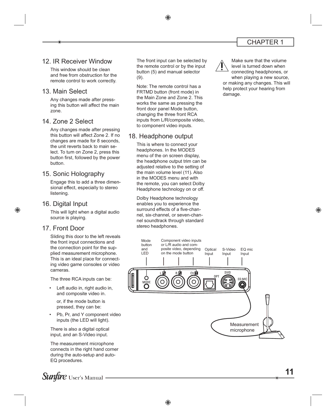
Sliding this door to the left reveals the front input connections and the connection point for the sup- plied measurement microphone. This is an ideal place for connect- ing video game consoles or video cameras.
The three RCA inputs can be:
•Left audio in, right audio in, and composite video in.
or, if the mode button is pressed, they can be:
•Pb, Pr, and Y component video inputs (the LED will light).
There is also a digital optical input, and an
The measurement microphone connects in the right hand corner during the
![]()
![]() User's Manual
User's Manual
18. Headphone output
This is where to connect your headphones. In the MODES menu of the on screen display, the headphone output trim can be adjusted relative to the setting of the main volume level (11). Also in the MODES menu and with the remote, you can select Dolby Headphone technology on or off.
Dolby Headphone technology enables you to experience the surround effects of a
Mode | Component video inputs |
|
|
|
|
|
|
|
|
|
|
|
|
|
|
|
|
|
|
| |||||||||
button | or L/R audio and com- |
|
|
|
|
|
|
|
|
|
|
|
|
|
|
|
|
|
|
| |||||||||
and | posite video, depending | Optical | EQ mic | ||||||||||||||||||||||||||
LED | on the mode button | Input | Input | Input | |||||||||||||||||||||||||
|
|
|
|
|
|
|
|
|
|
|
|
|
|
|
|
|
|
|
|
|
|
|
|
|
|
|
|
|
|
|
|
|
|
|
|
|
|
|
|
|
|
|
|
|
|
|
|
|
|
|
|
|
|
|
|
|
|
|
|
|
|
|
|
|
|
|
|
|
|
|
|
|
|
|
|
|
|
|
|
|
|
|
|
|
|
|
|
|
|
|
|
|
|
|
|
|
|
|
|
|
|
|
|
|
|
|
|
|
|
|
|
|
|
|
|
|
|
|
|
|
|
|
|
|
|
|
|
|
|
|
|
|
|
|
|
|
|
|
|
|
|
|
|
|
|
|
|
|
|
|
|
|
|
|
|
|
|
|
|
|
|
|
|
|
|
|
|
|
|
|
|
|
|
|
|
|
|
|
|
|
|
|
|
|
|
|
|
|
|
|
|
|
|
|
|
|
|
|
|
|
|
|
|
|
|
|
|
|
|
|
|
|
|
|
|
|
|
|
|
|
|
|
|
|
|
|
|
|
|
|
|
|
|
|
|
|
|
|
|
|
|
|
|
|
|
|
|
|
|
|
|
|
|
|
|
|
|
|
|
|
|
|
|
|
|
|
|
|
|
Measurement microphone
11
