Disassembly/Reassembly, and Adjustment (cont)
Step 5 - Front Caster Cover |
|
Disassembly |
|
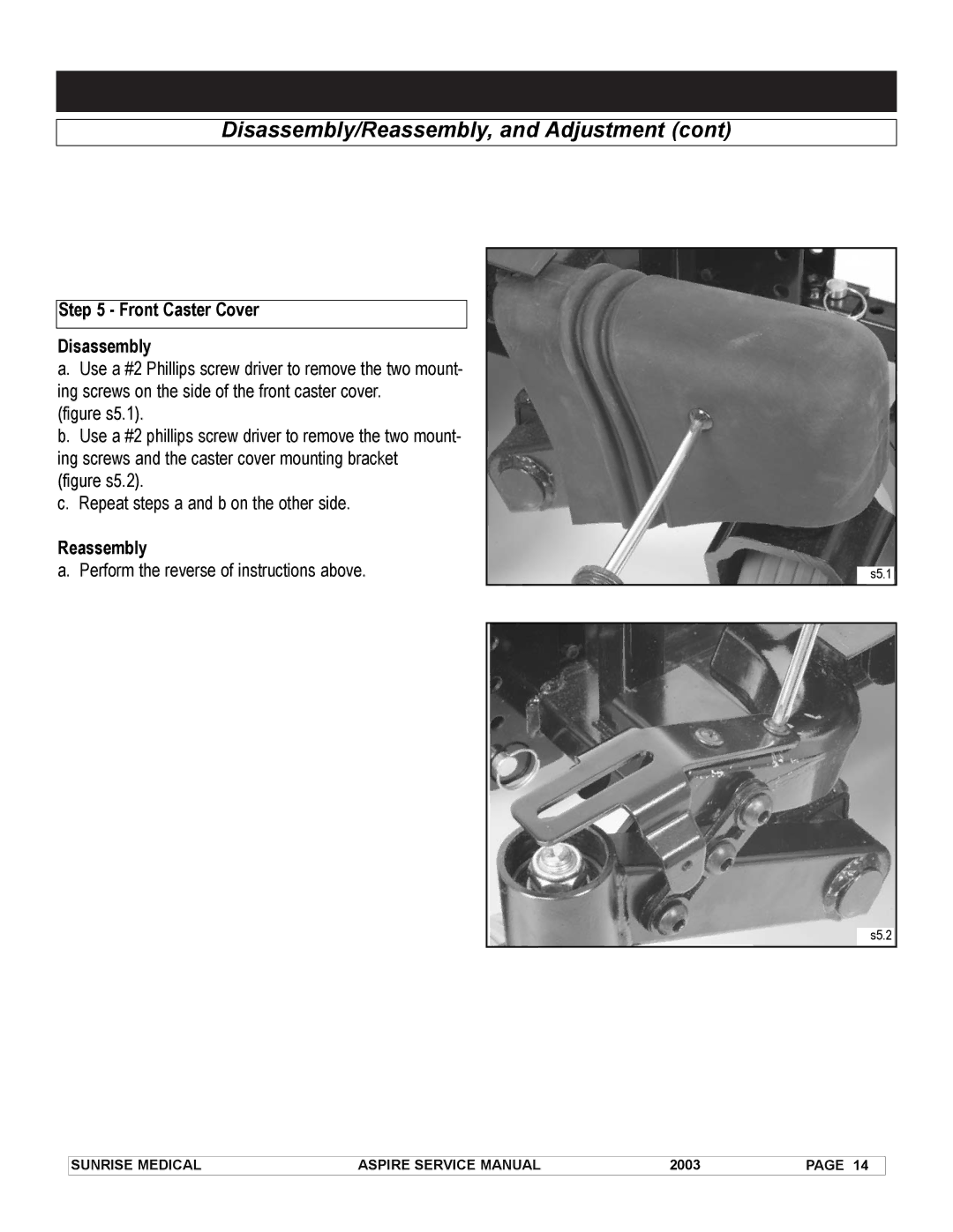
a. Use a #2 Phillips screw driver to remove the two mount- |
|
ing screws on the side of the front caster cover. |
|
(figure s5.1). |
|
b. Use a #2 phillips screw driver to remove the two mount- |
|
ing screws and the caster cover mounting bracket |
|
(figure s5.2). |
|
c. Repeat steps a and b on the other side. |
|
Reassembly |
|
a. Perform the reverse of instructions above. | s5.1 |
s5.2
SUNRISE MEDICAL | ASPIRE SERVICE MANUAL | 2003 | PAGE 14 |