Contents
Guardian Aspire Service Manual
2003 Sunrise Medical Inc. 931157 Rev A
Specifications
Guardian Aspire Troubleshooting Guide
Understanding VSI Controller Diagnostics Codes
Troubleshooting - No Power
SUNRISE MEDICAL
INTRODUCTION
ASPIRE SERVICE MANUAL
2003
Speed/Profile indicator
VSI Controller
Battery Condition Meter
Speed/ Profile Increase. Used to Increase the Speed/ Profile setting
24 Vdc
Plugs/Connectors
0 Vdc
LH Motor
Main Wiring Diagram/Tool List
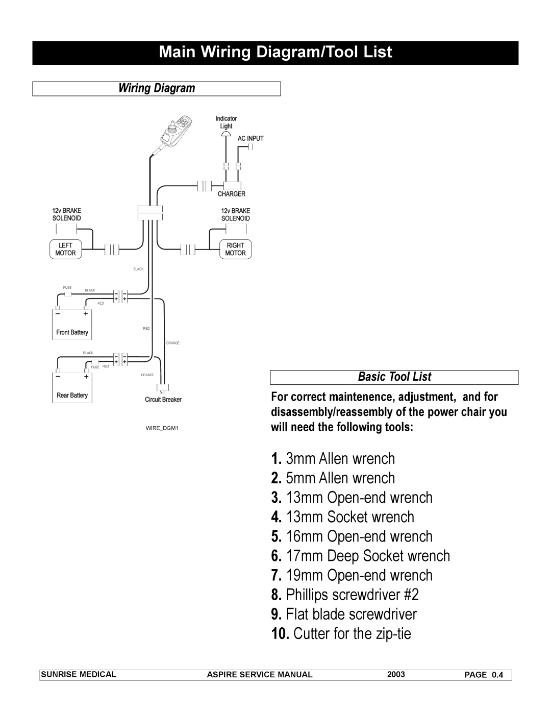
1.0 Circuit Breaker Reset
Section
Troubleshooting No Power
1.2 Battery Test
1.4 Not Charging
1.5 Battery Connection Check
1.3 Re-Charging the Batteries
A1.5.1
1.7 Battery Fuse
1.6 Battery Wire Harness
If polarity is reversed correct battery wiring
If the meter reads more than one ohm, change the Battery fuse
2.3 Battery Gauge is Steady This indicates that all is well
2.1 The Maximum Speed Indicator Ripples
2.2 The Maximum Speed Indicator Flashes
2.4 Battery Gauge Flashes Slowly
If none of the above corrects the problem, replace the left motor
Understanding VSI Controller Diagnostics Codes
3.1 One Bar - Low Battery Voltage
Section
Understanding VSI Controller Diagnostics Codes cont
3.3 Three Bars - Left Motor Wiring Trip
Test Left Motor Short
Understanding VSI Controller Diagnostics Codes cont
3.4 Four Bars- Right Motor Disconnected
Test Right Motor Open
Understanding VSI Controller Diagnostics Codes cont
3.5 Five Bars - Right Motor Wiring Trip
Test Right Motor Short
3.7 Eight Bars - Possible Control System Trip
Understanding VSI Controller Diagnostics Codes cont
3.6 Seven Bars - Possible Joystick Trip
3.8 Nine Bars - Solenoid Brake Trip
Battery Fault
Understanding VSI Controller Diagnostics Codes cont
3.9 Ten Bars - High Battery Voltage
3.8 Nine Bars - Solenoid Brake Trip cont
Reassembly
Disassembly/Reassembly, and Adjustment
Disassembly
Adjustment
Disassembly/Reassembly, and Adjustment cont
figure s4.1
Disassembly/Reassembly, and Adjustment cont
s5.1
s5.2
Disassembly/Reassembly, and Adjustment cont
s6.1 s6.2 s7.1
Disassembly/Reassembly, and Adjustment cont
s8.1 s8.2 s8.3
Disassembly/Reassembly, and Adjustment cont
a. Use a 5mm allen wrench and 13mm wrench to remove
Disassembly/Reassembly, and Adjustment cont
s10.1 s10.2 s10.3
Disassembly/Reassembly, and Adjustment cont
s11.1 s11.2 s11.3