Chapter 5: Advanced Serverboard Setup
5-8 Connector Definitions
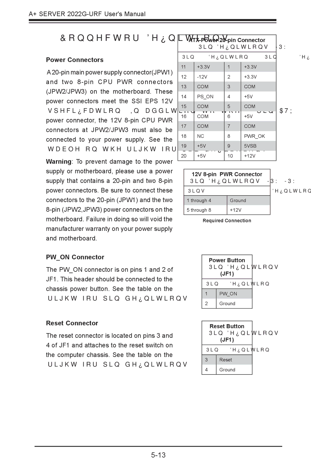
Power Connectors
A
Warning: To prevent damage to the power supply or motherboard, please use a power supply that contains a
ATX Power
Pin Definitions (JPW1)
Pin# |
| Definition | Pin # |
| Definition | |
11 |
| +3.3V |
| 1 |
| +3.3V |
|
|
| ||||
12 |
|
| 2 |
| +3.3V | |
13 |
| COM |
| 3 |
| COM |
14 |
| PS_ON |
| 4 |
| +5V |
15 |
| COM |
| 5 |
| COM |
16 |
| COM |
| 6 |
| +5V |
17 |
| COM |
| 7 |
| COM |
18 |
| NC |
| 8 |
| PWR_OK |
19 |
| +5V |
| 9 |
| 5VSB |
20 |
| +5V |
| 10 |
| +12V |
|
|
|
|
|
|
|
12V | |
Pin Definitions (JPW2/JPW3) | |
Pins | Definition |
|
|
1 through 4 | Ground |
5 through 8 | +12V |
|
|
Required Connection
PW_ON Connector
The PW_ON connector is on pins 1 and 2 of JF1. This header should be connected to the chassis power button. See the table on the right for pin definitions.
Reset Connector
The reset connector is located on pins 3 and 4 of JF1 and attaches to the reset switch on the computer chassis. See the table on the right for pin definitions.
Power Button
Pin Definitions
(JF1)
Pin# Definition
1PW_ON
2Ground
Reset Button
Pin Definitions
(JF1)
Pin# Definition
3Reset
4Ground