A+ SERVER
T-SGPIO
The
UIO Power Connector
A Universal I/O (UIO) Power connector is located next to the UID switch. Connect this connector to the power supply to provide adequate power to the UIO device installed on the slot for this device to function properly.
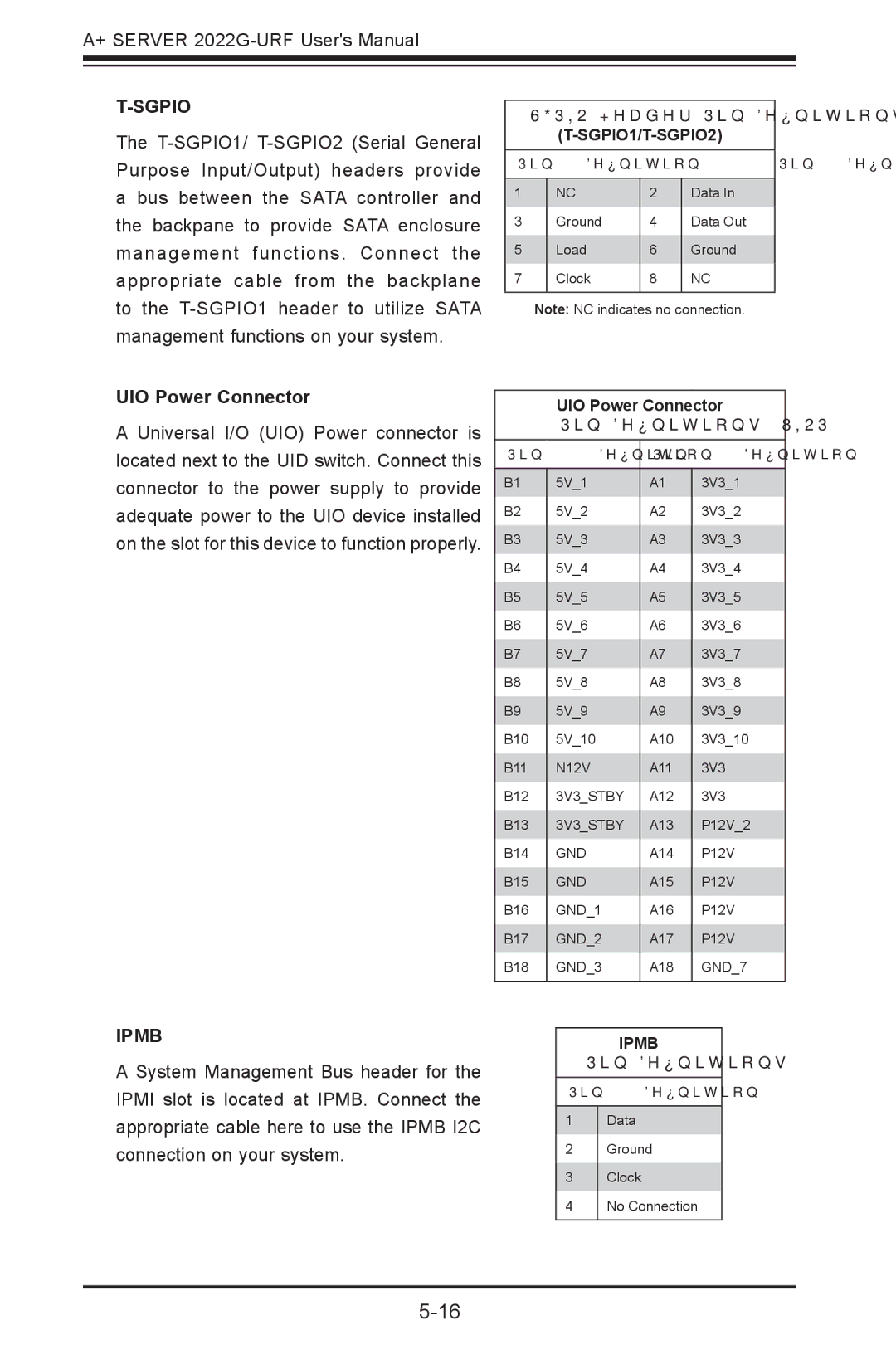
SGPIO Header Pin Definitions
(T-SGPIO1/T-SGPIO2)
Pin# | Definition | Pin# | Definition |
|
|
|
|
1 | NC | 2 | Data In |
3 | Ground | 4 | Data Out |
5 | Load | 6 | Ground |
7 | Clock | 8 | NC |
|
|
|
|
Note: NC indicates no connection.
UIO Power Connector
Pin Definitions (UIOP)
Pin# | Definition | Pin# | Definition |
|
|
|
|
B1 | 5V_1 | A1 | 3V3_1 |
B2 | 5V_2 | A2 | 3V3_2 |
B3 | 5V_3 | A3 | 3V3_3 |
B4 | 5V_4 | A4 | 3V3_4 |
B5 | 5V_5 | A5 | 3V3_5 |
B6 | 5V_6 | A6 | 3V3_6 |
B7 | 5V_7 | A7 | 3V3_7 |
B8 | 5V_8 | A8 | 3V3_8 |
B9 | 5V_9 | A9 | 3V3_9 |
B10 | 5V_10 | A10 | 3V3_10 |
B11 | N12V | A11 | 3V3 |
B12 | 3V3_STBY | A12 | 3V3 |
B13 | 3V3_STBY | A13 | P12V_2 |
B14 | GND | A14 | P12V |
B15 | GND | A15 | P12V |
B16 | GND_1 | A16 | P12V |
B17 | GND_2 | A17 | P12V |
B18 | GND_3 | A18 | GND_7 |
|
|
|
|
IPMB
A System Management Bus header for the IPMI slot is located at IPMB. Connect the appropriate cable here to use the IPMB I2C connection on your system.
IPMB
Pin Definitions
Pin# Definition
1Data
2Ground
3Clock
4No Connection