5013C-M8 specifications
Super Micro Computer 5013C-M8 is an enterprise-grade server chassis designed to provide robust performance, scalability, and reliability for a wide range of applications, including virtualization, cloud computing, and large-scale data processing. Its compact 1U form factor makes it an ideal choice for data centers and businesses looking to optimize space without compromising on power or functionality.One of the standout features of the 5013C-M8 is its versatile support for multiple Intel Xeon Scalable processors. This allows users to select processors that best fit their workload requirements, ranging from single-socket configurations for smaller applications to dual-socket setups for more demanding tasks. With the capability to support up to 512 GB of DDR4 memory, the chassis allows for high memory bandwidth and capacity, which is crucial for memory-intensive applications.
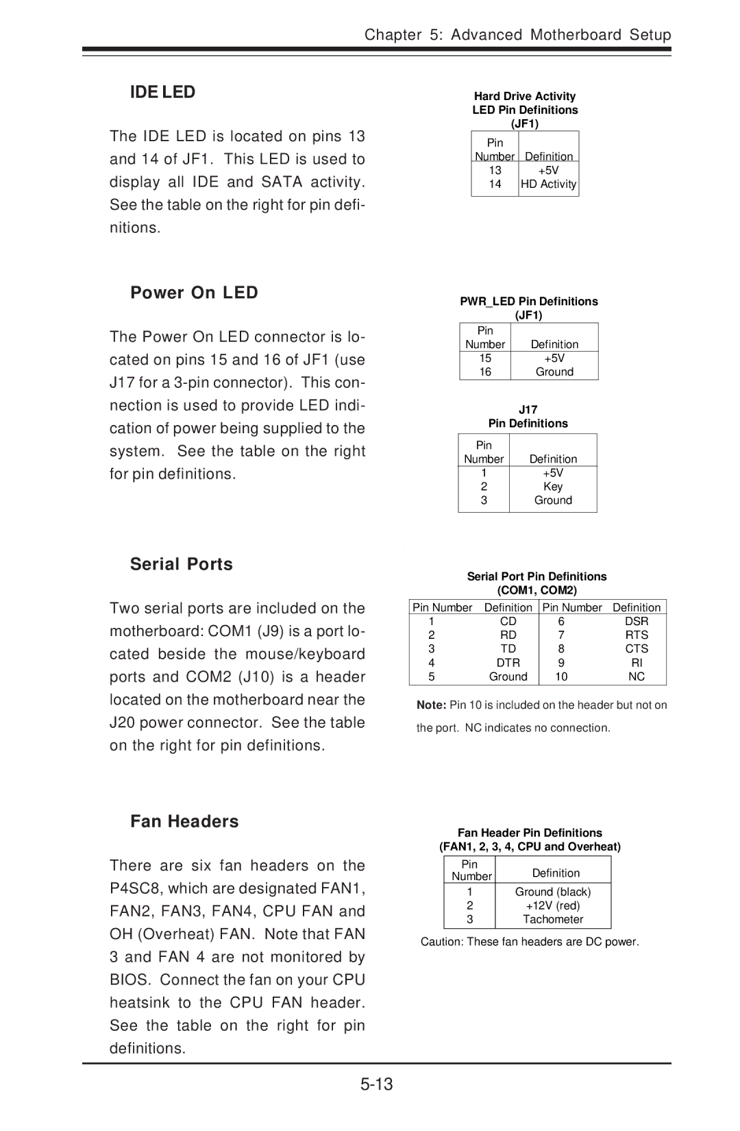
The Super Micro 5013C-M8 is engineered with a high-performance thermal management system. It comes equipped with multiple hot-swappable fans that ensure optimal airflow and cooling, which is essential for maintaining system stability and longevity under heavy loads. Furthermore, the chassis supports redundant power supplies, enhancing reliability by ensuring that downtime is minimized even in the event of a power supply failure.
Storage capabilities in the 5013C-M8 are expansive, featuring support for a combination of SATA, SAS, and NVMe drives. This flexibility allows organizations to tailor their storage solutions to meet specific performance and capacity needs, from traditional hard drives to cutting-edge SSDs for high-speed data access.
In terms of connectivity, the 5013C-M8 is fitted with multiple PCIe slots. This enables users to add a variety of expansion cards, including high-speed networking cards, GPUs for AI and machine learning applications, or additional storage controllers. This modularity ensures that the chassis can evolve alongside the business, adapting to new technologies and requirements as they arise.
Moreover, Super Micro emphasizes security and management features in the 5013C-M8. It offers a dedicated management interface that supports IPMI, allowing for remote monitoring and management of system health and performance metrics. This functionality is crucial for administrators looking to maintain and troubleshoot servers without needing physical access to the hardware.
In summary, the Super Micro Computer 5013C-M8 stands out for its reliable build quality, expansive scalability, and a versatile feature set, making it an excellent choice for organizations looking to invest in a powerful and adaptable server chassis capable of meeting modern computing demands.

