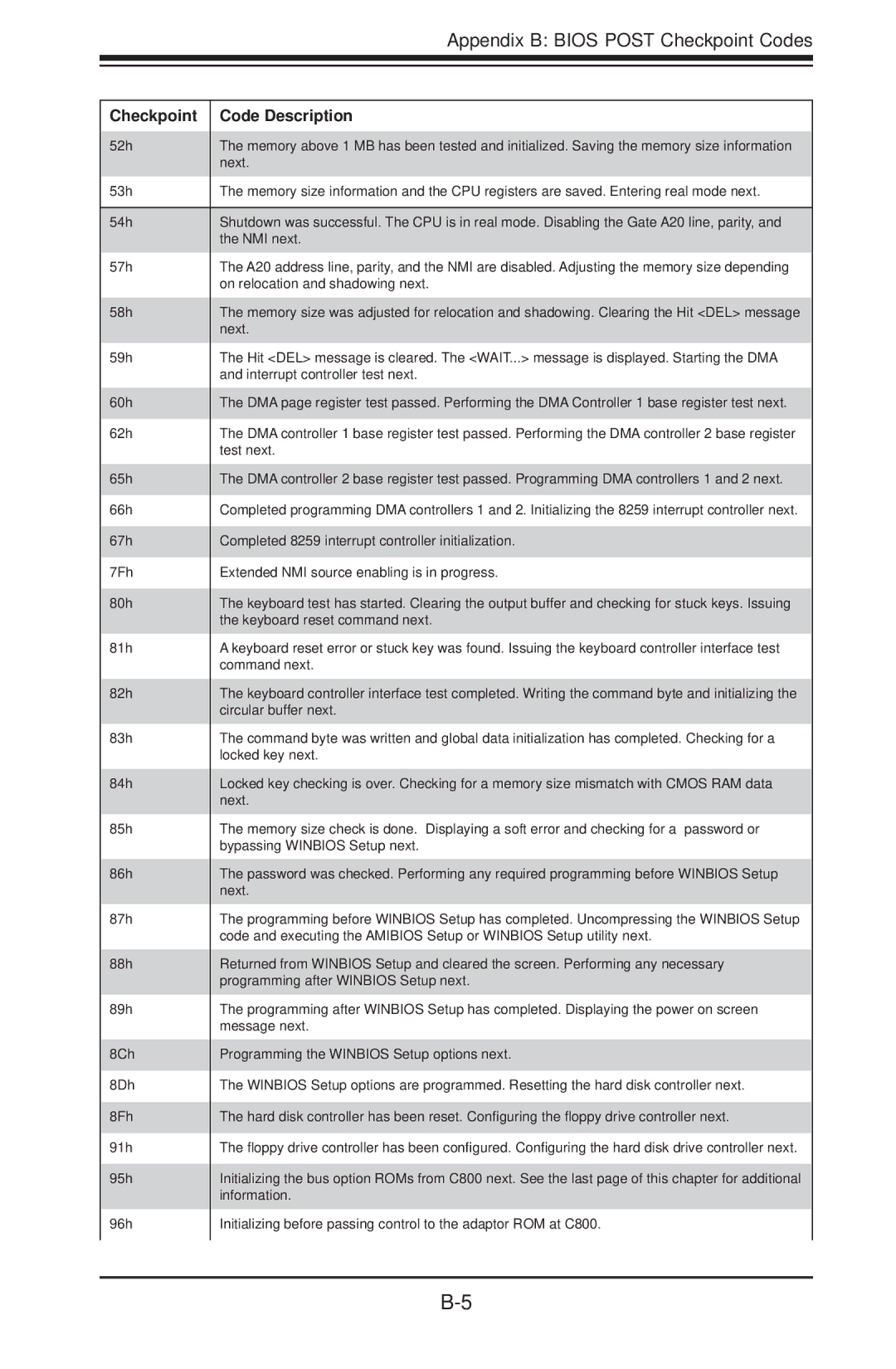
Appendix B: BIOS POST Checkpoint Codes


Checkpoint

Code Description

52h

The memory above 1 MB has been tested and initialized. Saving the memory size information


next.

53h

The memory size information and the CPU registers are saved. Entering real mode next.


54h

Shutdown was successful. The CPU is in real mode. Disabling the Gate A20 line, parity, and


the NMI next.

57h

The A20 address line, parity, and the NMI are disabled. Adjusting the memory size depending


on relocation and shadowing next.

58h

The memory size was adjusted for relocation and shadowing. Clearing the Hit <DEL> message


next.

59h

The Hit <DEL> message is cleared. The <WAIT...> message is displayed. Starting the DMA


and interrupt controller test next.

60h

The DMA page register test passed. Performing the DMA Controller 1 base register test next.

62h

The DMA controller 1 base register test passed. Performing the DMA controller 2 base register


test next.

65h

The DMA controller 2 base register test passed. Programming DMA controllers 1 and 2 next.

66h

Completed programming DMA controllers 1 and 2. Initializing the 8259 interrupt controller next.

67h

Completed 8259 interrupt controller initialization.

7Fh

Extended NMI source enabling is in progress.

80h

The keyboard test has started. Clearing the output buffer and checking for stuck keys. Issuing


the keyboard reset command next.

81h

A keyboard reset error or stuck key was found. Issuing the keyboard controller interface test


command next.

82h

The keyboard controller interface test completed. Writing the command byte and initializing the


circular buffer next.

83h

The command byte was written and global data initialization has completed. Checking for a


locked key next.

84h

Locked key checking is over. Checking for a memory size mismatch with CMOS RAM data


next.

85h

The memory size check is done. Displaying a soft error and checking for a password or


bypassing WINBIOS Setup next.

86h

The password was checked. Performing any required programming before WINBIOS Setup


next.

87h

The programming before WINBIOS Setup has completed. Uncompressing the WINBIOS Setup


code and executing the AMIBIOS Setup or WINBIOS Setup utility next.

88h

Returned from WINBIOS Setup and cleared the screen. Performing any necessary


programming after WINBIOS Setup next.

89h

The programming after WINBIOS Setup has completed. Displaying the power on screen


message next.

8Ch

Programming the WINBIOS Setup options next.

8Dh

The WINBIOS Setup options are programmed. Resetting the hard disk controller next.

8Fh

The hard disk controller has been reset. Configuring the floppy drive controller next.

91h

The floppy drive controller has been configured. Configuring the hard disk drive controller next.

95h

Initializing the bus option ROMs from C800 next. See the last page of this chapter for additional


information.

96h

Initializing before passing control to the adaptor ROM at C800.


B-5

Page 81
Image 81
SUPER MICRO Computer H8SCM-F user manual Checkpoint Code Description

H8SCM, H8SCM-F specifications

Super Micro Computer, known for its cutting-edge server technology and enterprise solutions, offers the H8SCM-F and H8SCM motherboards as part of its robust line of products designed for high-performance computing tasks. These motherboards are ideal for businesses that require reliable, scalable, and cost-effective solutions for their data center and server needs.

The H8SCM-F and H8SCM motherboards are based on the AMD Opteron architecture, which delivers an impressive performance-to-cost ratio. They support dual-socket configurations, accommodating up to 16 cores in a single system, which is ideal for handling intensive processing demands. This allows organizations to run virtualization software, database applications, and other resource-heavy tasks with ease.

One of the standout features of the H8SCM-F motherboard is its extensive memory support. It can accommodate up to 512GB of DDR3 memory across eight DIMM slots. This high memory capacity enhances performance, particularly in data-intensive applications, ensuring that users can run multiple processes without facing bottlenecks.

The H8SCM series motherboards also emphasize connectivity. With integrated features such as dual Gigabit Ethernet ports, they support effective bandwidth management. Additionally, the presence of multiple PCI-E slots enables users to incorporate various expansion cards for enhanced connectivity options, including additional network interfaces and high-performance storage controllers.

In terms of storage, the H8SCM-F motherboard offers support for multiple SATA drives, facilitating RAID configurations for improved data redundancy and performance. The ability to implement RAID 0, 1, 5, and 10 provides users with flexibility and security for their data storage needs.

Another key technology integrated into the H8SCM series is advanced thermal management. Supermicro has designed these motherboards with careful attention to airflow and cooling solutions, ensuring that systems remain stable under heavy workloads. This is particularly vital in environments where uptime is critical.

In summary, the Super Micro Computer H8SCM-F and H8SCM motherboards are designed with high-performance, scalability, and reliability in mind. Their support for powerful AMD Opteron processors, substantial memory capacity, extensive connectivity options, and advanced storage and thermal management features make them an excellent choice for businesses seeking efficient server solutions. Whether for virtualized environments or high-demand applications, these motherboards deliver exceptional performance and versatility to meet a wide range of enterprise needs.