a.

c.

b.


d.

b.

a.

d.

c.

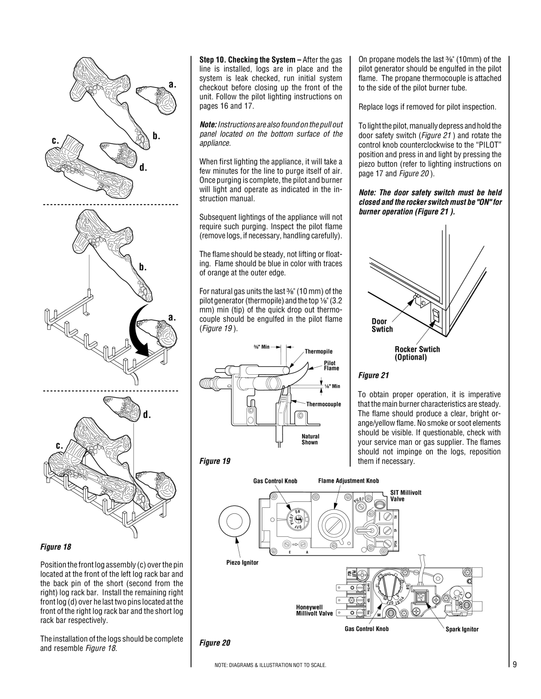
Step 10. Checking the System – After the gas line is installed, logs are in place and the system is leak checked, run initial system checkout before closing up the front of the unit. Follow the pilot lighting instructions on pages 16 and 17.

Note: Instructions are also found on the pull out panel located on the bottom surface of the appliance.

When first lighting the appliance, it will take a few minutes for the line to purge itself of air. Once purging is complete, the pilot and burner will light and operate as indicated in the in- struction manual.

Subsequent lightings of the appliance will not require such purging. Inspect the pilot flame (remove logs, if necessary, handling carefully).

The flame should be steady, not lifting or float- ing. Flame should be blue in color with traces of orange at the outer edge.

For natural gas units the last ³⁄₈" (10 mm) of the pilot generator (thermopile) and the top ¹⁄₈" (3.2

mm)min (tip) of the quick drop out thermo- couple should be engulfed in the pilot flame (Figure 19 ).

³⁄₈" Min

Thermopile

Pilot

Flame

¹⁄₈" Min

Thermocouple

Natural

Shown

Figure 19

On propane models the last ³⁄₈" (10mm) of the pilot generator should be engulfed in the pilot flame. The propane thermocouple is attached to the side of the pilot burner tube.

Replace logs if removed for pilot inspection.

To light the pilot, manually depress and hold the door safety switch (Figure 21 ) and rotate the control knob counterclockwise to the “PILOT” position and press in and light by pressing the piezo button (refer to lighting instructions on page 17 and Figure 20 ).

Note: The door safety switch must be held closed and the rocker switch must be "ON" for burner operation (Figure 21 ).

Door

Swtich

Rocker Swtich (Optional)

Figure 21

To obtain proper operation, it is imperative that the main burner characteristics are steady. The flame should produce a clear, bright or- ange/yellow flame. No smoke or soot elements should be visible. If questionable, check with your service man or gas supplier. The flames should not impinge on the logs, reposition them if necessary.

Figure 18

Position the front log assembly (c) over the pin located at the front of the left log rack bar and the back pin of the short (second from the right) log rack bar. Install the remaining right front log (d) over he last two pins located at the front of the right log rack bar and the short log rack bar respectively.

The installation of the logs should be complete and resemble Figure 18.

Gas Control Knob

Flame Adjustment Knob


IL

SIT Millivolt


Valve


OT


P


T

O N


it


TH

L


O


I


P

FFO


TP


TPTH

EA

Piezo Ignitor


O


N


L


P

O


H


I

I


L


O


FFO T


Honeywell


Millivolt Valve


Gas Control Knob


Spark Ignitor

Figure 20

NOTE: DIAGRAMS & ILLUSTRATION NOT TO SCALE.

9

Page 9
Image 9
Superior CF5500-CMP, CF6500-CMP, CF5500-CMN, CF6500-CMN Replace logs if removed for pilot inspection, Door Swtich

CF6500-CMP, CF5500-CMP, CF6500-CMN, CF5500-CMN specifications

The Superior CF5500-CMN, CF6500-CMP, CF5500-CMP, and CF6500-CMN are cutting-edge products recognized for their exceptional performance and efficiency in various applications. These models cater to diverse user requirements, making them ideal for different sectors such as manufacturing, healthcare, and commercial settings.

One of the prominent features of the Superior CF series is its robust build quality. Each model is constructed using high-grade materials that ensure durability and longevity, even under rigorous operating conditions. This makes the CF series an excellent investment for businesses seeking reliable and long-lasting equipment.

The CF5500-CMN and CF6500-CMN models are particularly known for their compact design, which allows for easy integration into existing systems without occupying excessive space. This characteristic is especially beneficial for environments where space is at a premium, as it maximizes operational efficiency without compromising performance.

Innovation is at the heart of Superior technologies. The CF series incorporates advanced thermal management systems that enhance cooling efficiency, allowing the devices to operate effectively while minimizing energy consumption. This is an essential factor in today’s eco-conscious climate, where businesses aim to reduce their carbon footprint.

The CF6500-CMP and CF5500-CMP models are equipped with user-friendly interfaces that streamline operation and simplify programming. This feature is designed to enhance user experience and reduce the learning curve associated with adopting new technology. With intuitive controls, operators can easily navigate settings and adjust parameters to suit their specific needs.

In addition to their ease of use, these models come equipped with a range of safety features designed to protect both the equipment and users. Built-in alarms and automatic shutdown mechanisms prevent overheating and other potentially dangerous conditions, ensuring a safe working environment.

Furthermore, the Superior CF series is designed to be highly adaptable. With modular components, users can easily upgrade or customize their systems, allowing for future-proofing and scalability in response to changing demands. This adaptability ensures that businesses can keep pace with technological advancements without the need for complete system overhauls.

To sum up, the Superior CF5500-CMN, CF6500-CMP, CF5500-CMP, and CF6500-CMN stand out for their remarkable build quality, innovative technologies, user-friendly design, and enhanced safety features. These characteristics make them reliable choices for businesses seeking efficient and effective solutions to meet their operational needs. Investing in the Superior CF series is a step toward achieving greater productivity and sustainability in the modern workplace.