Danaher Motion Superior Electric
3.3.2 Power Input
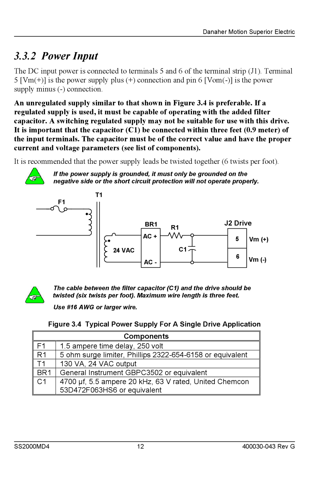
The DC input power is connected to terminals 5 and 6 of the terminal strip (J1). Terminal 5 [Vm(+)] is the power supply plus (+) connection and pin 6
An unregulated supply similar to that shown in Figure 3.4 is preferable. If a regulated supply is used, it must be capable of operating with the added filter capacitor. A switching regulated supply may not be suitable for use with this drive. It is important that the capacitor (C1) be connected within three feet (0.9 meter) of the input terminals. The capacitor must be of the correct value and have the proper current and voltage parameters (see list of components).
It is recommended that the power supply leads be twisted together (6 twists per foot).
If the power supply is grounded, it must only be grounded on the negative side or the short circuit protection will not operate properly.
T1
F1
24 VAC |
BR1 | R1 | J2 Drive | |
|
|
| |
AC + |
| 5 | Vm (+) |
|
| ||
| C1 | 6 |
|
AC - |
| Vm | |
|
| ||
|
|
| |
The cable between the filter capacitor (C1) and the drive should be twisted (six twists per foot). Maximum wire length is three feet.
Use #16 AWG or larger wire.
Figure 3.4 Typical Power Supply For A Single Drive Application
| Components |
F1 | 1.5 ampere time delay, 250 volt |
R1 | 5 ohm surge limiter, Phillips |
T1 | 130 VA, 24 VAC output |
BR1 | General Instrument GBPC3502 or equivalent |
C1 | 4700 µf, 5.5 ampere 20 kHz, 63 V rated, United Chemcon |
| 53D472F063HS6 or equivalent |
SS2000MD4 | 12 |