Manuals
/
Swann
/
Home Audio
/
Home Theater System
Swann
H.264
manual
The Rear Panel of the DVR, English
Models:
H.264
1
7
60
60
Download
60 pages
36.73 Kb
4
5
6
7
8
9
10
11
Troubleshooting
Specs
Install
Connection Diagram
Alarm: Video Loss see page
Connecting the DVR
Warranty
Maintenance
General Configuration
Playback Problems?
Page 7
Image 7
Page 6
Page 8
Page 7
Image 7
Page 6
Page 8
Contents
4 or 8 Channel H.264 DVR
English
English
English
Before You Begin
IMPORTANT SAFETY INSTRUCTIONS
DEFAULT PASSWORD INFORMATION
Reference
Contents
English
Introduction
Stage 1. Connecting the DVR page 6 to page
Introduction
The Basic Setup
Getting the DVR Setup
English
Installation Guidelines
• Only install the DVR in a well ventilated space
• Use only the supplied power adapter
Connecting the DVR
Front Panel of the DVR
English
English
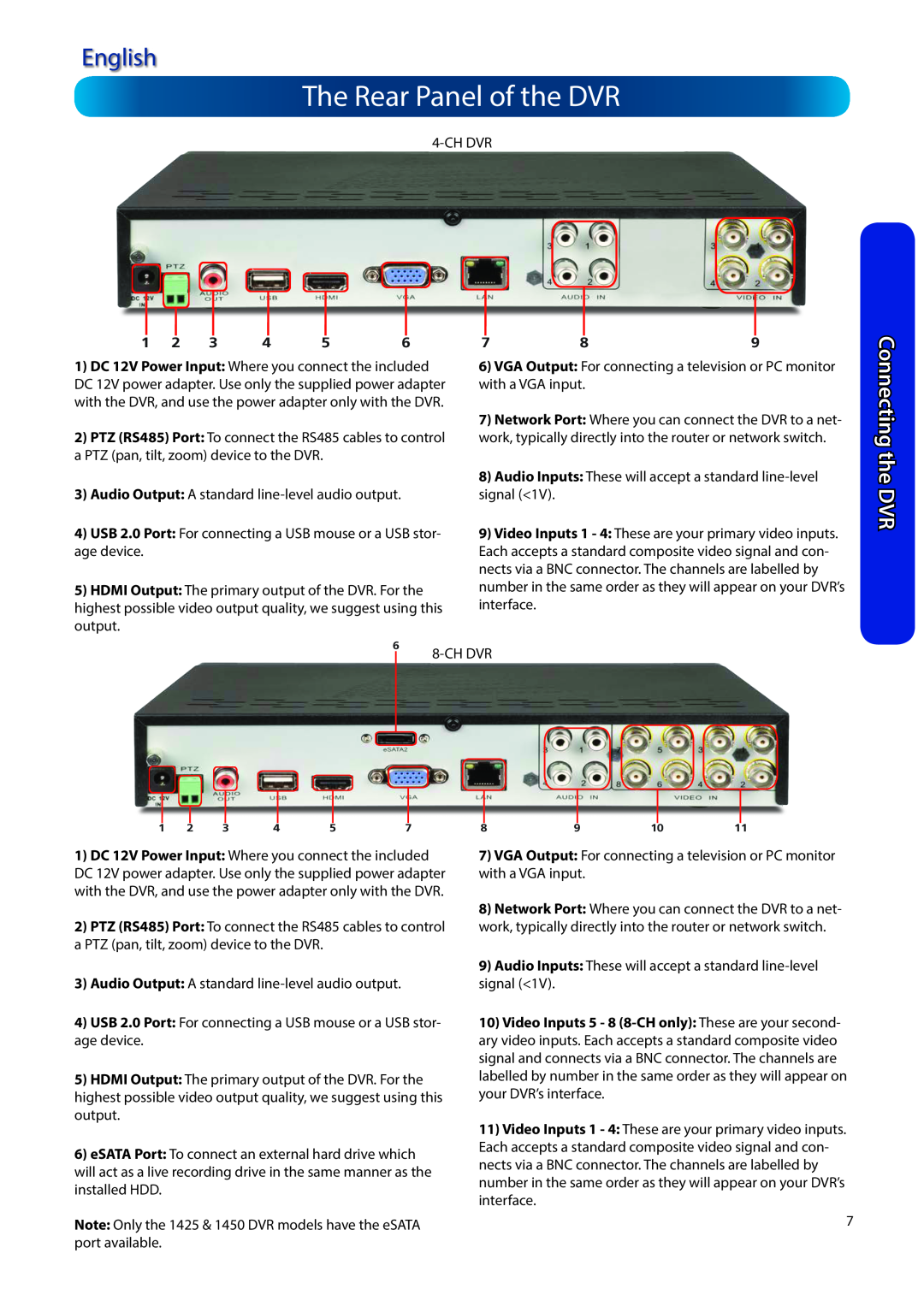
The Rear Panel of the DVR
Connecting the DVR
Connection Diagram
English
Connecting the DVR
Connecting Additional Devices
English
The Remote Control
Default Password Information
Basic DVR Operation
Basic Setup
Setting up a Dynamic DNS for remote access
Basic Setup: General
Basic Setup
•Setting the Date, Time and your Time Zone
English
Basic Setup: HDD & Networking
Basic Setup
Network Access
English
Basic Setup: DDNS & Email
Basic Setup
Enable SSL or TLS: Enable
English
Basic Setup: NTP & DST
Basic Setup
DST Configuration
Finishing the Setup Wizard
Basic Setup: Account Configuration & Completion
Basic Setup
Account Configuration
How to install MyDVR
Basic Setup: Installing MyDVR on PC
Got a Mac?
Basic Setup
If you’re accessing the DVR via the Internet
MyDVR: Logging In
Default Password Information
Basic Setup
English
MyDVR Interface
Need more details?
Basic Setup
English
MyDVR: Local Configuration
Playback Problems?
Basic Setup
Recording: Advanced Config see page
MyDVR Configuration Overview
Basic Setup
Display: Channel Settings see page
•Email Setting see page
Basic Setup
Network: Advanced Config see page
•NTP Setup see page
Alarm: Exception see page
Basic Setup
Alarm: Motion Detection see page
Alarm: Video Loss see page
System General see page
Basic Setup
English
Device: PTZ see page
Basic Setup
Remote Access From a Mobile Device
English
English
Default Password Information
Operating the DVR Locally
Basic Setup
Shutdown
Menu Layout
BasicSetup
English
Advanced Configuration include
Advanced Configuration
Advanced Configuration
By Default
Advanced Configuration
Display: Camera
English
Standard 4:3 - 1024 x
Display: Output
Advanced Configuration
English
Advanced Configuration
Recording: Encode
English
Advanced Configuration
Recording: Option
English
Important Guidelines
Recording: Schedule
Advanced Configuration
English
English
Search: Playback
Advanced Configuration
using at the time
The Backup File List
Search: Backup
Advanced Configuration
To backup footage
English
Search: Event
Search: Log Search
Advanced Configuration
Remember: Playback Limitations
The Playback Interface
Advanced Configuration
English
Advanced Configuration
Network: General
English
What port numbers should I use?
Network: Advanced
Advanced Configuration
English
English
Network: Advanced: DDNS
Network: Advanced: NTP
Configuration
English
Network: Advanced: IP Filter
Network: Network Status
Advanced Configuration
Gmail Google
Network: Advanced: Email Settings
Advanced Configuration
English
How Motion Detection Works
Alarm: Motion
Advanced Configuration
English
To set the MOTION DETECTION AREA
Alarm: Motion Detection Configuration
Advanced Configuration
English
Motion Detection Compatibility
Alarm: Motion Detection Notes
Advanced Configuration
English
Alarm: Video Loss
Alarm: Motion Detection - Action
Alarm: Video Loss
Advanced Configuration
Advanced Configuration
Alarm: Exception
English
English
Device: HDD
Device: S.M.A.R.T
Advanced Configuration
Note for Remote Access and Mobile Device users
Device: PTZ
Advanced Configuration
PTZ Settings
support this function
Advanced Configuration
English
PTZ Controls
Advanced Configuration
System: General
English
Advanced Configuration
System User
English
Advanced Configuration
System: System Information
English
•Choose Configuration: Import/Export
System: Maintenance
Advanced Configuration
To export your settings
English
Troubleshooting
Reference
Routers
Addendum: Third Party Hardware
English
Reference
Reference
Technical Specifications
Get up to Date Information
English
Reference
Warranty Information
Warranty Terms & Conditions
English
English
Notes
English
AllCountries E-mail:tech@swann.com
Helpdesk / TechnicalSupport Details
English
Swann Technical Support
Top
Page
Image
Contents