Main
Page
Page
ii DS6707 Digital Imager Scanner Product Reference Guide
Page
Page
Table of Contents
vi DS6707 Digital Imager Scanner Product Reference Guide
Table of Contents vii
viii DS6707 Digital Imager Scanner Product Reference Guide
Table of Contents ix
x DS6707 Digital Imager Scanner Product Reference Guide
Table of Contents xi
xii DS6707 Digital Imager Scanner Product Reference Guide
Page
Page
About This Guide
Configurations
Chapter Descriptions
xvi DS6707 Digital Imager Scanner Product Reference Guide
Notational Conventions
- - - -
- -
- - -
*
Related Documents
Service Information
Symbol Global Interaction Center
xviii DS6707 Digital Imager Scanner Product Reference Guide
About This Guide xix
Getting Started
Getting Started 1 - 2
Supported Interfaces
Unpacking
1 - 3 DS6707 Digital Imager Scanner Product Reference Guide
Setting Up the Digital Imager Scanner
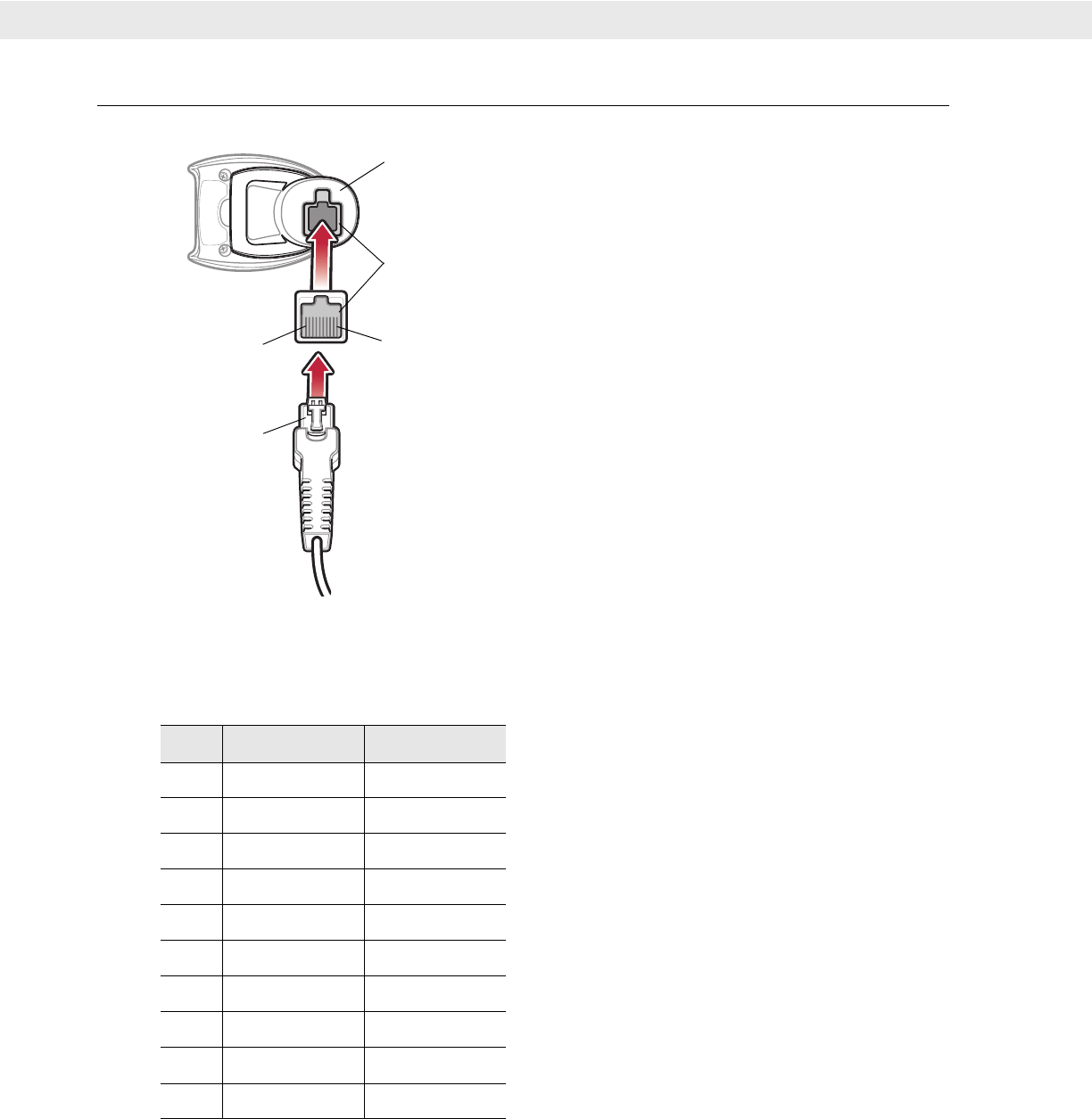
Installing the Interface Cable
Removing the Interface Cable
Getting Started 1 - 4
Connecting Power (if required)
Mounting the Digital Imager Scanner
Desk Mount
1 - 5 DS6707 Digital Imager Scanner Product Reference Guide
Wall Mount
Scanning
2 - 2 DS6707 Digital Imager Scanner Product Reference Guide
Beeper Definitions
Scanning 2 - 3
2 - 4 DS6707 Digital Imager Scanner Product Reference Guide
LED Definitions
Scanning in Hand-Held Mode
Scanning with the Digital Imager Scanner
Scanning 2 - 5
Aiming
2 - 6 DS6707 Digital Imager Scanner Product Reference Guide
Scanning in Hands-Free Mode
Page
Page
Chapter 3
Maintenance & Technical Specifications
Chapter 3
Maintenance
3 - 2 DS6707 Digital Imager Scanner Product Reference Guide
Troubleshooting
Maintenance & Technical Specifications 3 - 3
3 - 4 DS6707 Digital Imager Scanner Product Reference Guide
Technical Specifications
Maintenance & Technical Specifications 3 - 5
3 - 6 DS6707 Digital Imager Scanner Product Reference Guide
Maintenance & Technical Specifications 3 - 7
Digital Imager Scanner Signal Descriptions
Page
Chapter 4
User Preferences & Miscellaneous Digital Imager Scanner Options
Chapter 4
*
4 - 2 DS6707 Digital Imager Scanner Product Reference Guide
User Preferences and Miscellaneous Options - Parameter Defaults
User Preferences & Miscellaneous Digital Imager Scanner Options 4 - 3
User Preferences
Page
*
User Preferences & Miscellaneous Digital Imager Scanner Options 4 - 7
Time Delay to Low Power Mode Parameter # 92h
*
4 - 8 DS6707 Digital Imager Scanner Product Reference Guide
Trigger Mode Parameter # 8Ah
Time Delay to Low Power Mode (continued)
*
User Preferences & Miscellaneous Digital Imager Scanner Options 4 - 9
Picklist Mode Parameter # F0h 92h
*
Page
User Preferences & Miscellaneous Digital Imager Scanner Options 4 - 11
Beep After Good Decode Parameter # 38h
Decoding Illumination Parameter # F0h, 2Ah
*
Miscellaneous Scanner Parameters
4 - 14 DS6707 Digital Imager Scanner Product Reference Guide
Prefix/Suffix Values
To correct an error or change a selection, scan Cancel on page D-2.
User Preferences & Miscellaneous Digital Imager Scanner Options 4 - 15
Scan Data Transmission Format Parameter # EBh
*
4 - 16 DS6707 Digital Imager Scanner Product Reference Guide
FN1 Substitution Values Key Category Parameter # 67h Decimal Value Parameter # 6Dh
Scan Data Transmission Format (continued)
Page
Page
Chapter 5
Imaging Preferences
Chapter 5
* Indicates Default *Enable Decode Aiming Pattern
5 - 2 DS6707 Digital Imager Scanner Product Reference Guide
Imaging Preferences Parameter Defaults
Imaging Preferences 5 - 3
5 - 4 DS6707 Digital Imager Scanner Product Reference Guide
Imaging Preferences
Operational Modes
Decode Mode
Snapshot Mode
Imaging Preferences 5 - 5
*
5 - 6 DS6707 Digital Imager Scanner Product Reference Guide
Image Capture Illumination Parameter # F0h, 69h
Fixed Exposure Parameter #: F4h F1h 37h
*
Imaging Preferences 5 - 7
Fixed Gain Parameter #: F1h 38h
Gain / Exposure Priority for Snapshot Mode Parameter # F1h, 32h
Page
Imaging Preferences 5 - 9
Snapshot Aiming Pattern Parameter # F0h, 2Ch
Image Cropping Parameter # F0h, 2Dh
*
Page
Imaging Preferences 5 - 11
Image Size (Number of Pixels) Parameter # F0h, 2Eh
*
5 - 12 DS6707 Digital Imager Scanner Product Reference Guide
Image Brightness (Target White) Parameter # F0h 86h
JPEG Image Options Parameter # F0h, 2Bh
*
Imaging Preferences 5 - 13
JPEG Target File Size Parameter # F4h, F1h, 31h
JPEG Quality and Size Value JPEG Quality = Parameter # F0h, 31h
*
Image Enhancement Parameter # F1h, 34h
*
5 - 16 DS6707 Digital Imager Scanner Product Reference Guide
Bits Per Pixel Parameter # F0h, 2Fh
*
Imaging Preferences 5 - 17
Signature Capture Parameter # 5Dh
Output File Format
*
Imaging Preferences 5 - 19
Signature Capture Bits Per Pixel Parameter # F0h, 3Ah
Page
*
Page
SSI Interface
6 - 2 DS6707 Digital Imager Scanner Product Reference Guide
Connecting Using Simple Serial Interface
SSI Interface 6 - 3
Simple Serial Interface Default Parameters
6 - 4 DS6707 Digital Imager Scanner Product Reference Guide
SSI Host Parameters
Baud Rate Parameter # 9Ch
*
SSI Interface 6 - 5
Baud Rate (continued)
6 - 6 DS6707 Digital Imager Scanner Product Reference Guide
Parity Parameter # 9Eh
SSI Interface 6 - 7
Check Parity Parameter # 97h
Software Handshaking Parameter # 9Fh
Page
*
6 - 10 DS6707 Digital Imager Scanner Product Reference Guide
Host Serial Response Time-out Parameter # 9Bh
*
SSI Interface 6 - 11
Host Character Time-out Parameter # EFh
*
6 - 12 DS6707 Digital Imager Scanner Product Reference Guide
Multipacket Option Parameter # F0h, 4Eh
*
SSI Interface 6 - 13
Interpacket Delay Parameter # F0h, 4Fh
*
6 - 14 DS6707 Digital Imager Scanner Product Reference Guide
Event Reporting
Decode Event Parameter # F0h, 00h
*
Page
USB Interface
7 - 2 DS6707 Digital Imager Scanner Product Reference Guide
Connecting a USB Interface
- -
USB Interface 7 - 3
USB Parameter Defaults
7 - 4 DS6707 Digital Imager Scanner Product Reference Guide
USB Host Parameters
USB Device Type
Select the desired USB device type.
*
7 - 6 DS6707 Digital Imager Scanner Product Reference Guide
USB Country Keyboard Types (Country Codes)
*
Page
7 - 8 DS6707 Digital Imager Scanner Product Reference Guide
USB Keystroke Delay
USB CAPS Lock Override
*
USB Interface 7 - 9
USB Ignore Unknown Characters
Emulate Keypad
*
Page
USB Interface 7 - 11
Function Key Mapping
Simulated Caps Lock
*
7 - 12 DS6707 Digital Imager Scanner Product Reference Guide
ASCII Character Set for USB
Convert Case
*
USB Interface 7 - 13
7 - 14 DS6707 Digital Imager Scanner Product Reference Guide
USB Interface 7 - 15
7 - 16 DS6707 Digital Imager Scanner Product Reference Guide
USB Interface 7 - 17
7 - 18 DS6707 Digital Imager Scanner Product Reference Guide
USB Interface 7 - 19
7 - 20 DS6707 Digital Imager Scanner Product Reference Guide
USB Interface 7 - 21
7 - 22 DS6707 Digital Imager Scanner Product Reference Guide
RS-232 Interface
8 - 2 DS6707 Digital Imager Scanner Product Reference Guide
Connecting an RS-232 Interface
RS-232 Interface 8 - 3
RS-232 Parameter Defaults
8 - 4 DS6707 Digital Imager Scanner Product Reference Guide
RS-232 Host Parameters
RS-232 Interface 8 - 5
RS-232 Host Parameters (continued)
8 - 6 DS6707 Digital Imager Scanner Product Reference Guide
RS-232 Host Types
RS-232 Host Types (continued)
Page
RS-232 Interface 8 - 9
Parity
8 - 10 DS6707 Digital Imager Scanner Product Reference Guide
Stop Bit Select
Data Bits
*
RS-232 Interface 8 - 11
Check Receive Errors
Hardware Handshaking
*
8 - 12 DS6707 Digital Imager Scanner Product Reference Guide
Hardware Handshaking (continued)
RS-232 Interface 8 - 13
Software Handshaking
8 - 14 DS6707 Digital Imager Scanner Product Reference Guide
Software Handshaking (continued)
-
RS-232 Interface 8 - 15
Host Serial Response Time-out
*
8 - 16 DS6707 Digital Imager Scanner Product Reference Guide
RTS Line State
Beep on <BEL>
*
Page
8 - 18 DS6707 Digital Imager Scanner Product Reference Guide
Nixdorf Beep/LED Options
Ignore Unknown Characters
*
RS-232 Interface 8 - 19
ASCII Character Set for RS-232
8 - 20 DS6707 Digital Imager Scanner Product Reference Guide
RS-232 Interface 8 - 21
8 - 22 DS6707 Digital Imager Scanner Product Reference Guide
RS-232 Interface 8 - 23
Page
Chapter 9
123Scan
Chapter 9
Communication with 123Scan
Page
Chapter 10
Symbologies
Chapter 10
*
10 - 2 DS6707 Digital Imager Scanner Product Reference Guide
Symbology Parameter Defaults
Symbologies 10 - 3
10 - 4 DS6707 Digital Imager Scanner Product Reference Guide
Symbologies 10 - 5
UPC/EAN
Page
*
Symbologies 10 - 9
Decode UPC/EAN/JAN Supplementals Parameter # 10h
Page
*
10 - 12 DS6707 Digital Imager Scanner Product Reference Guide
Transmit UPC-E1 Check Digit Parameter # 2Ah
UPC-A Preamble Parameter # 22h
*
Symbologies 10 - 13
UPC-E Preamble Parameter # 23h
10 - 14 DS6707 Digital Imager Scanner Product Reference Guide
UPC-E1 Preamble Parameter # 24h
Convert UPC-E to UPC-A Parameter # 25h
*
10 - 16 DS6707 Digital Imager Scanner Product Reference Guide
UCC Coupon Extended Code Parameter # 55h
Code 128
*
Code 39
*
10 - 20 DS6707 Digital Imager Scanner Product Reference Guide
Convert Code 39 to Code 32 Parameter # 56h
Code 32 Prefix Parameter # E7h
*
Symbologies 10 - 21
Set Lengths for Code 39 Parameter # L1 = 12h, L2 = 13h
*
Symbologies 10 - 23
Transmit Code 39 Check Digit Parameter # 2Bh
Scan a bar code below to transmit Code 39 data with or without the check digit.
Code 39 Full ASCII Conversion Parameter # 11h
*
10 - 24 DS6707 Digital Imager Scanner Product Reference Guide
Code 39 Buffering (Scan & Store) Parameter # 71h
Buffer Data
*
Symbologies 10 - 25
Clear Transmission Buffer
Transmit Buffer
10 - 26 DS6707 Digital Imager Scanner Product Reference Guide
Overfilling Transmission Buffer
Attempt to Transmit an Empty Buffer
Symbologies 10 - 27
Code 93
Enable/Disable Code 93 Parameter # 09h
Set Lengths for Code 93 Parameter # L1 = 1Ah, L2 = 1Bh
*
Page
Symbologies 10 - 29
Code 11
Code 11 Parameter # 0Ah
Set Lengths for Code 11 Parameter # L1 = 1Ch, L2 = 1Dh
*
Page
Symbologies 10 - 31
This feature selects whether or not to transmit the Code 11 check digit(s).
Code 11 Check Digit Verification
Transmit Code 11 Check Digits Parameter # 2Fh
*
10 - 32 DS6707 Digital Imager Scanner Product Reference Guide
Interleaved 2 of 5 (ITF)
Enable/Disable Interleaved 2 of 5 Parameter # 06h
Set Lengths for Interleaved 2 of 5 Parameter # L1 = 16h, L2 = 17h
Page
Page
*
10 - 36 DS6707 Digital Imager Scanner Product Reference Guide
Discrete 2 of 5 (DTF)
Enable/Disable Discrete 2 of 5 Parameter # 05h
Set Lengths for Discrete 2 of 5 Parameter # L1 = 14h, L2 = 15h
*
Page
10 - 38 DS6707 Digital Imager Scanner Product Reference Guide
Codabar (NW - 7)
Enable/Disable Codabar Parameter # 07h
Set Lengths for Codabar Parameter # L1 = 18h, L2 = 19h
Page
*
Symbologies 10 - 41
MSI
Enable/Disable MSI Parameter # 0Bh
Set Lengths for MSI Parameter # L1 = 1Eh, L2 = 1Fh
Page
*
Postal Codes
Page
Page
*
RSS (Reduced Space Symbology)
Parameter # F0h 54h
*
Composite
*
Symbologies 10 - 51
Composite TLC-39 Parameter # F0h 73h
UPC Composite Mode Parameter # F0h 58h
*
2D Symbologies
*
10 - 54 DS6707 Digital Imager Scanner Product Reference Guide
Code 128 Emulation Parameter # 7Bh
*
Page
Symbologies 10 - 57
Redundancy Level
Parameter # 4Eh
Redundancy Level 1
Redundancy Level 2
Redundancy Level 3
Redundancy Level (continued)
Redundancy Level 4
*
Symbologies 10 - 59
Security Level
Parameter # 4Dh
*
Symbologies 10 - 61
Report Version
Macro PDF Features
Flush Macro Buffer
Abort Macro PDF Entry
Page
Chapter 11
Advanced Data Formatting
Chapter 11
Rules: Criteria Linked to Actions
11 - 2 DS6707 Digital Imager Scanner Product Reference Guide
Using ADF Bar Codes
ADF Bar Code Menu Example
Advanced Data Formatting 11 - 3
Rule 1: The Code 128 Scanning Rule
Rule 2: The UPC Scanning Rule
Alternate Rule Sets
11 - 4 DS6707 Digital Imager Scanner Product Reference Guide
Rules Hierarchy (in Bar Codes)
Advanced Data Formatting 11 - 5
Default Rules
Special Commands
Pause Duration
Begin New Rule
Page
Page
11 - 8 DS6707 Digital Imager Scanner Product Reference Guide
Criteria
Code Types
Page
Page
Page
Page
Advanced Data Formatting 11 - 13
Code Types (continued)
11 - 14 DS6707 Digital Imager Scanner Product Reference Guide
Code Lengths
Page
Page
Page
11 - 18 DS6707 Digital Imager Scanner Product Reference Guide
Message Containing A Specific Data String
Specific String at Start
Code Lengths (continued)
Advanced Data Formatting 11 - 19
Specific String, Any Location
Any Message OK
11 - 20 DS6707 Digital Imager Scanner Product Reference Guide
Numeric Keypad
Bar codes on this page should not be confused with those on the alphanumeric keyboard.
Page
Page
Advanced Data Formatting 11 - 23
Actions
Send Data
Page
Page
11 - 26 DS6707 Digital Imager Scanner Product Reference Guide
Setup Field(s)
Send Data (continued)
Advanced Data Formatting 11 - 27
11 - 28 DS6707 Digital Imager Scanner Product Reference Guide
Skip Ahead
Use the following bar codes to skip ahead characters.
Advanced Data Formatting 11 - 29
Page
Advanced Data Formatting 11 - 31
Modify Data
11 - 32 DS6707 Digital Imager Scanner Product Reference Guide
Advanced Data Formatting 11 - 33
Pad Data with Spaces
Page
Page
Page
Page
Page
Page
Page
Page
Page
Page
Page
Page
Page
Advanced Data Formatting 11 - 47
Page
Page
Page
Page
Page
Page
Page
Page
Page
Page
Page
Page
Page
Page
Page
Page
Page
Page
Page
Page
Page
Page
Page
Page
Page
Page
Page
Page
Page
Page
11 - 78 DS6707 Digital Imager Scanner Product Reference Guide
Send Right Control Key
The Send Right Control Key action will send a tap (press and release) of the Right Control Key.
Send Function Key (continued)
Advanced Data Formatting 11 - 79
Send Graphic User Interface (GUI) Characters
Page
Page
Page
Page
Page
Page
11 - 86 DS6707 Digital Imager Scanner Product Reference Guide
Alphanumeric Keyboard
Page
Page
Advanced Data Formatting 11 - 89
Alphanumeric Keyboard (continued)
11 - 90 DS6707 Digital Imager Scanner Product Reference Guide
Alphanumeric Keyboard (continued)
Page
Page
Page
Page
Page
Page
Page
Page
Page
Page
Appendix A
Standard Default Parameters
Appendix A
A - 2 DS6707 Digital Imager Scanner Product Reference Guide
Appendix A: Standard Default Parameters A - 3
A - 4 DS6707 Digital Imager Scanner Product Reference Guide
Appendix A: Standard Default Parameters A - 5
A - 6 DS6707 Digital Imager Scanner Product Reference Guide
Appendix A: Standard Default Parameters A - 7
A - 8 DS6707 Digital Imager Scanner Product Reference Guide
Appendix B
Programming Reference
Appendix B
Symbol Code Identifiers
B - 2 DS6707 Digital Imager Scanner Product Reference Guide
Appendix B: Programming Reference B - 3
AIM Code Identifiers
B - 4 DS6707 Digital Imager Scanner Product Reference Guide
Appendix B: Programming Reference B - 5
B - 6 DS6707 Digital Imager Scanner Product Reference Guide
Appendix B: Programming Reference B - 7
Page
Appendix C
Sample Bar Codes
Appendix C
Code 39
UPC/EAN
UPC-A, 100%
Code 128
Interleaved 2 of 5
Page
Page
Page
Page
Numeric Bar Codes
Numeric Bar Codes
Page
Appendix E
ASCII Character Sets
Appendix E
E - 2 DS6707 Digital Imager Scanner Product Reference Guide
Appendix E: ASCII Character Sets E - 3
E - 4 DS6707 Digital Imager Scanner Product Reference Guide
Appendix E: ASCII Character Sets E - 5
E - 6 DS6707 Digital Imager Scanner Product Reference Guide
Appendix E: ASCII Character Sets E - 7
E - 8 DS6707 Digital Imager Scanner Product Reference Guide
Page
E - 10 DS6707 Digital Imager Scanner Product Reference Guide
Appendix E: ASCII Character Sets E - 11
E - 12 DS6707 Digital Imager Scanner Product Reference Guide
Glossary
A
B
Glossary - 2
C
Glossary - 3
D
Glossary - 4
E
F
H
Glossary - 5
I
Glossary - 6
K
L
M
Glossary - 7
N
O
P
Glossary - 8
Q
R
Glossary - 9
S
Glossary - 10
T
Page
Page
Index
Numerics
A
Index - 2 DS6707 Digital Imager Scanner Product Reference Guide
B
Index - 3
C
Index - 4 DS6707 Digital Imager Scanner Product Reference Guide
D
E
F
G
H
L
M
N
P
Q
V
W
Tell Us What You Think...