DH200RPL specifications
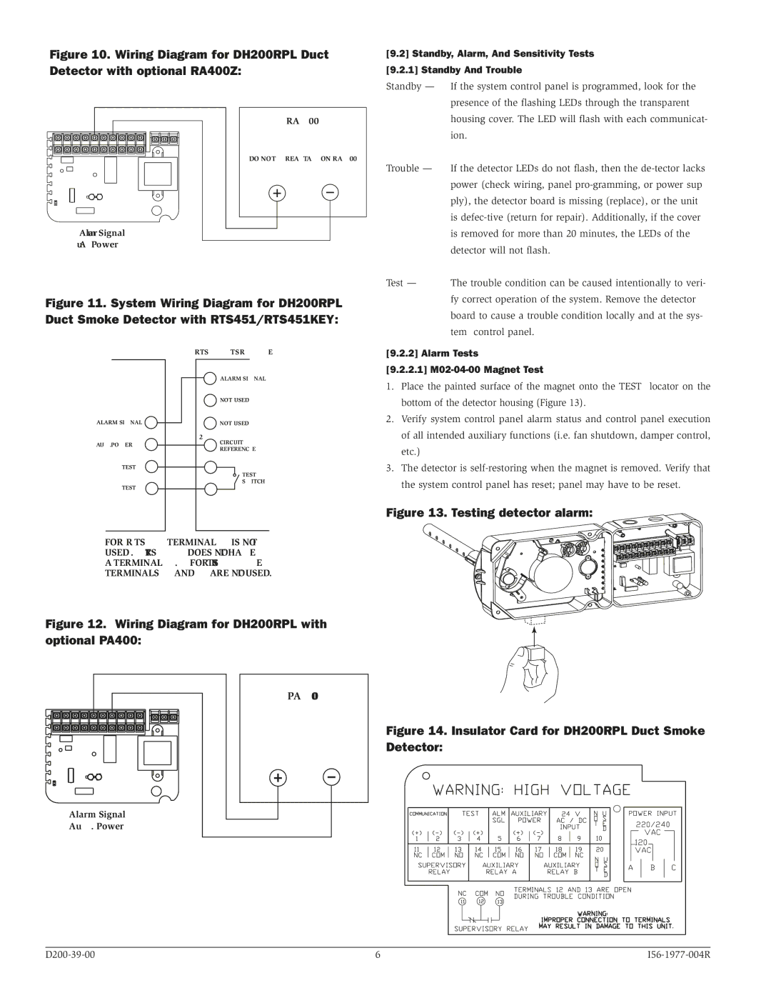
The System Sensor DH200RPL is a cutting-edge smoke detection sensor designed to enhance fire safety in a variety of environments. With a commitment to innovation and reliability, this sensor is engineered to meet the demands of both commercial and residential applications.One of the defining features of the DH200RPL is its dual detection technology, which utilizes both photoelectric and ionization sensing methods. This dual approach ensures that the sensor can effectively identify both smoldering and flaming fires, providing a comprehensive solution for smoke detection. The photoelectric component is particularly effective in detecting slow, smoldering fires, while the ionization part excels in identifying fast-flaming fires. This combination enhances the overall effectiveness of fire detection, offering peace of mind to users.
Additionally, the DH200RPL is equipped with advanced digital signal processing technology. This technology allows for improved sensitivity and a faster response time, ensuring that any potential smoke event is detected promptly. The sensor is also designed to minimize false alarms, addressing a common concern in smoke detection systems. By intelligently analyzing the environmental conditions, the DH200RPL can differentiate between actual smoke and non-threatening particles, reducing unnecessary alerts.
The sensor features a sleek, modern design that can seamlessly integrate into various settings without being obtrusive. It is compact and lightweight, making it easy to install in various locations. Furthermore, the DH200RPL is compatible with a wide range of existing fire alarm systems, providing flexibility for upgrades or new installations.
Another notable feature is its built-in connectivity options, allowing for integration with advanced fire alarm monitoring systems. This feature enhances the sensor’s functionality by enabling remote monitoring and alert notifications, ensuring that users are informed of any potential issues even when they are not on-site.
In conclusion, the System Sensor DH200RPL smoke detector stands out in the market due to its dual detection technology, advanced signal processing, and integration capabilities. Its efficient design and smart functionalities make it an ideal choice for ensuring safety in various environments, making it a trusted option for both homeowners and business operators alike. With the DH200RPL, users can rest assured that they are protected by one of the most reliable smoke detection technologies available today.

