Unpacking and Installation
TANDBERG ENTRYPOINT USER GUIDE
What’s in the Box? | Installation Site Preparations |
General Installation Precautions
To avoid damage to the unit during transportation, the Entrypoint is delivered in a special shipping box, which should contain the following components:
•Entrypoint Server
•Network cables
•ISDN cables (5m) (Qty 4) – only if the 3G/Audio GW 4xBRI option is chosen
•ISDN cables (5m) (Qty 1) – only if the 3G/Audio GW 1xPRI option is chosen
•Ethernet cable (5m).
•Power Cables
•Install Sheet
•User Manual CD
•Registration Card
•Accessories bag (Console cable, rack ears, rubber feet)
Please report any discrepancies to your TANDBERG representative immediately.
A brief, yet detailed presentation of the procedure to get you up and going can be found in the Installation Sheet accompanying your TANDBERG product.
•Make sure that the Entrypoint is accessible and that all cables can be easily connected.
•For ventilation: Leave a space of at least 10cm (4 inches) behind the Entrypoint’s rear panel and 10cm (4 inches) in front of the front panel.
•The room in which you install the Entrypoint should have an ambient temperature between 0ºC and 35ºC (32ºF and 95ºF) and between 10% and 90%
•Do not place heavy objects directly on top of the Entrypoint.
•Do not place hot objects directly on top, or directly beneath the Entrypoint.
•Use a grounded AC power outlet for the Entrypoint.
•You will need a CSU (Channel Service Unit) between your system and the PRI line from your network provider.
•Make sure that it is possible to receive and to make mobile (H.324M) video calls from behind this line. Check this with your network operator!
•If you are behind a PABX make sure that the PABX is capable of routing mobile (H.324M) video calls.
•Never install telephone wiring during a lightning storm.
•Never install telephone jacks in wet locations unless the jack is specifically designed for wet locations.
•Never touch uninstalled telephone wires or terminals unless the telephone line has been disconnected at the network interface.
•Use caution when installing or modifying telephone lines.
•Avoid using a telephone (other than a cordless type) during an electrical storm. There may be a remote risk of electrical shock from lightning.
•Do not use the telephone to report a gas leak in the vicinity of the leak.
•The socket outlet shall be installed near to the equipment and shall be easily accessible.
•Never install cables without first switching the power OFF.
•This product complies with directives: LVD 73/23/EC, EMC 89/366/EEC, R&TTE 99/5/EEC.
•This product complies with the standards
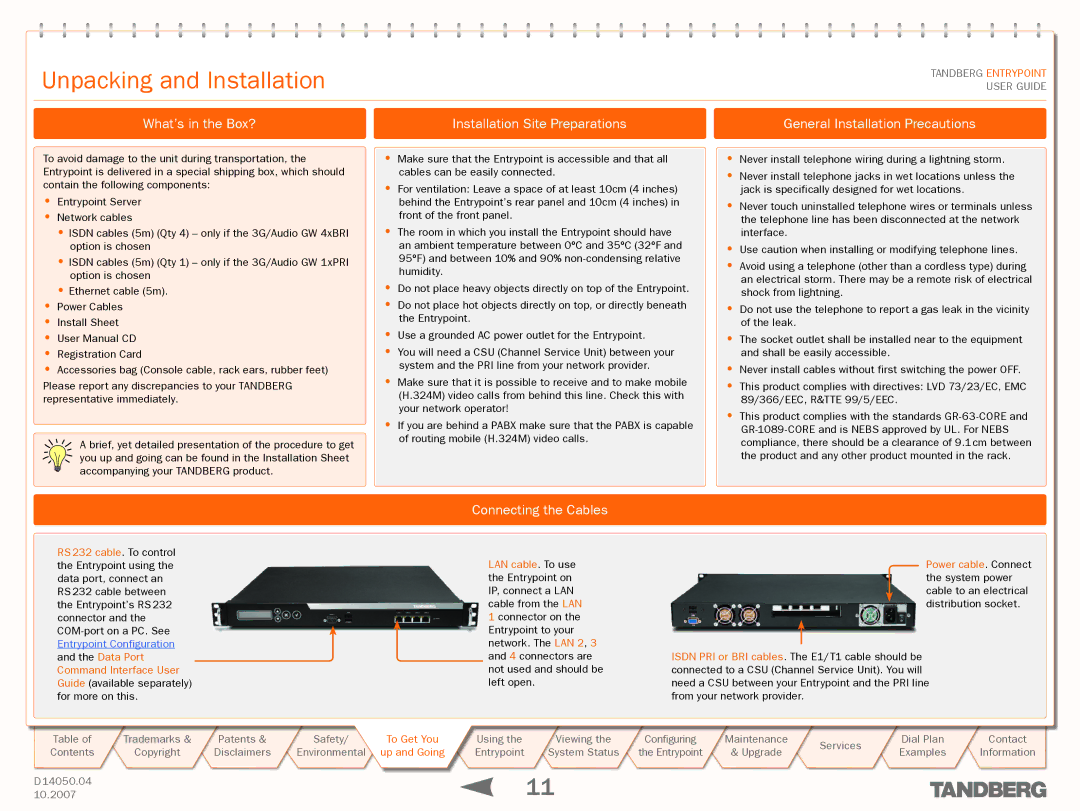
RS 232 cable. To control the Entrypoint using the data port, connect an RS 232 cable between the Entrypoint’s RS 232 connector and the
Connecting the Cables
LAN cable. To use the Entrypoint on IP, connect a LAN cable from the LAN 1 connector on the Entrypoint to your network. The LAN 2, 3 and 4 connectors are not used and should be left open.
Power cable. Connect the system power cable to an electrical distribution socket.
ISDN PRI or BRI cables. The E1/T1 cable should be connected to a CSU (Channel Service Unit). You will need a CSU between your Entrypoint and the PRI line from your network provider.