2 Operational Theory | Model 3020T | |
|
|
|
|
|
|
|
|
|
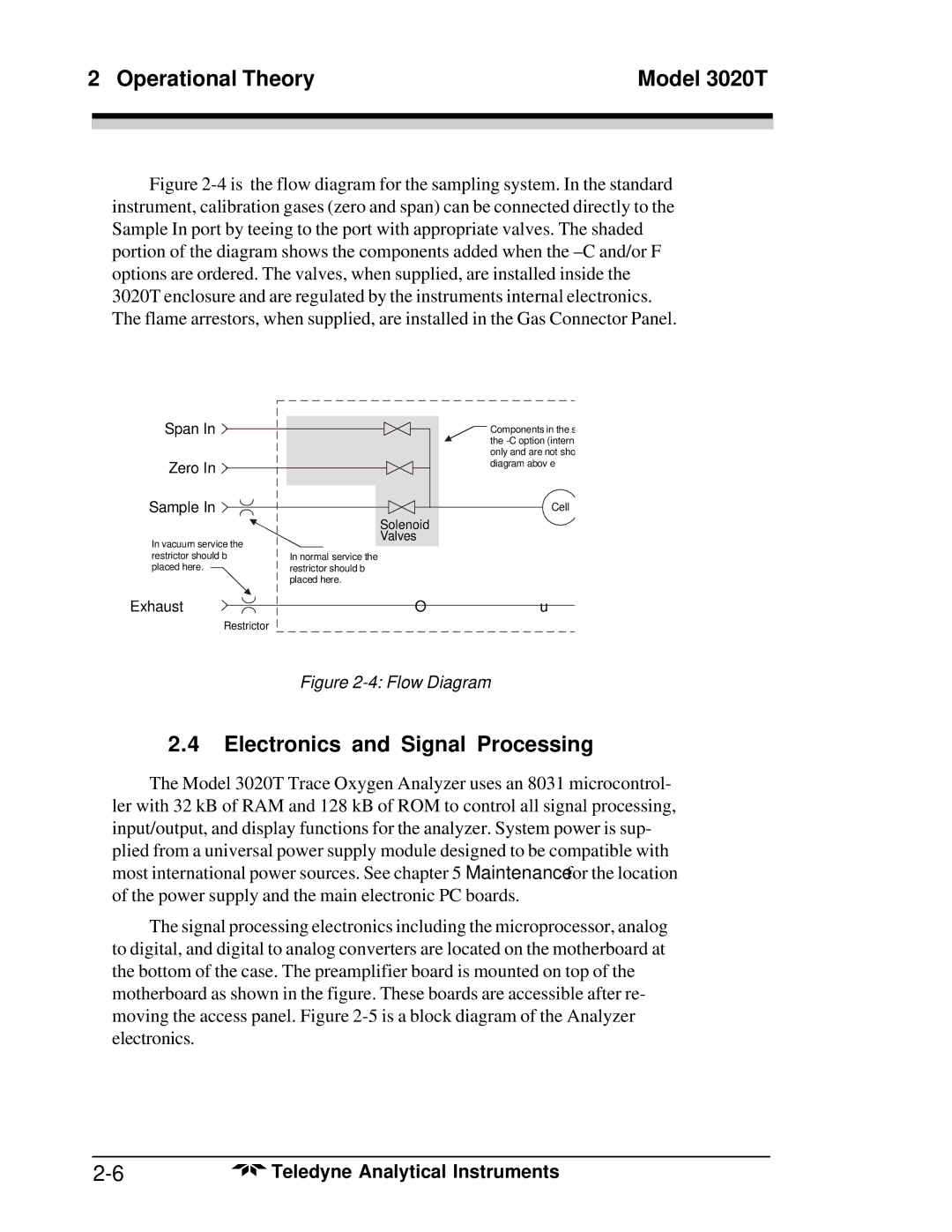
Figure 2-4 is the flow diagram for the sampling system. In the standard instrument, calibration gases (zero and span) can be connected directly to the Sample In port by teeing to the port with appropriate valves. The shaded portion of the diagram shows the components added when the –C and/or F options are ordered. The valves, when supplied, are installed inside the 3020T enclosure and are regulated by the instruments internal electronics. The flame arrestors, when supplied, are installed in the Gas Connector Panel.
Span In
Zero In
Sample In
In vacuum service the restrictor should b placed here. ![]()
![]() Components in the s the
Components in the s the
Cell
Solenoid
Valves
In normal service the restrictor should b placed here.
Exhaust
Restrictor
Ou
Figure 2-4: Flow Diagram
2.4Electronics and Signal Processing
The Model 3020T Trace Oxygen Analyzer uses an 8031 microcontrol- ler with 32 kB of RAM and 128 kB of ROM to control all signal processing, input/output, and display functions for the analyzer. System power is sup- plied from a universal power supply module designed to be compatible with most international power sources. See chapter 5 Maintenance for the location of the power supply and the main electronic PC boards.
The signal processing electronics including the microprocessor, analog to digital, and digital to analog converters are located on the motherboard at the bottom of the case. The preamplifier board is mounted on top of the motherboard as shown in the figure. These boards are accessible after re- moving the access panel. Figure
Teledyne Analytical Instruments |