Trace Oxygen Analyzer |
|
|
|
|
|
|
|
|
|
|
|
|
|
|
|
|
|
|
|
| Installation 3 | ||||||||||||||||||||||||||||
|
|
|
|
|
|
|
|
|
|
|
|
|
|
|
|
|
|
|
|
|
|
|
|
|
|
|
|
|
|
|
|
|
|
|
|
|
|
|
|
|
|
|
|
|
|
|
|
|
|
|
|
|
|
|
|
|
|
|
|
|
|
|
|
|
|
|
|
|
|
|
|
|
|
|
|
|
|
|
|
|
|
|
|
|
|
|
|
|
|
|
|
|
|
|
|
|
|
|
|
|
|
|
|
|
|
|
|
|
|
|
|
|
|
|
|
|
|
|
|
|
|
|
|
|
|
|
|
|
|
|
|
|
|
|
|
|
|
|
|
|
|
|
|
|
|
|
|
|
|
|
|
|
|
|
|
|
|
|
|
|
|
|
|
|
|
|
|
|
|
|
|
|
|
|
|
|
|
|
|
|
|
|
|
|
|
|
|
|
|
|
|
|
|
|
|
|
|
|
|
|
|
|
|
|
|
|
|
|
|
|
|
|
|
|
|
|
|
|
|
|
|
|
|
|
|
|
|
|
|
|
|
|
|
|
|
|
|
|
|
|
|
|
|
|
|
|
|
|
|
|
|
|
|
|
|
|
|
|
|
|
|
|
|
|
|
|
|
|
|
|
|
|
|
|
|
|
|
|
|
|
|
|
|
|
|
|
|
|
|
|
|
|
|
|
|
|
|
|
|
|
|
|
|
|
|
|
|
|
|
|
|
|
|
|
|
|
|
|
|
|
|
|
|
|
|
|
|
|
|
|
|
|
|
|
|
|
|
|
|
|
|
|
|
|
|
|
|
|
|
|
|
|
|
|
|
|
|
|
|
|
|
|
|
|
|
|
|
|
|
|
|
|
|
|
|
|
|
|
|
|
|
|
|
|
|
|
|
|
|
|
|
|
|
|
|
|
|
|
|
|
|
|
|
|
|
|
|
|
|
|
|
|
|
|
|
|
|
|
|
|
|
|
|
|
|
|
|
|
|
|
|
|
|
|
|
|
|
|
|
|
|
|
|
|
|
|
|
|
|
|
|
|
|
|
|
|
|
|
|
|
|
|
|
|
|
|
|
|
|
|
|
|
|
|
|
|
|
|
|
|
|
|
|
|
|
|
|
|
|
|
|
|
|
|
|
|
|
|
|
|
|
|
|
|
|
|
|
|
|
|
|
|
|
|
|
|
|
|
|
|
|
|
|
|
|
|
|
|
|
|
|
|
|
|
|
|
|
|
|
|
|
|
|
|
|
|
|
|
|
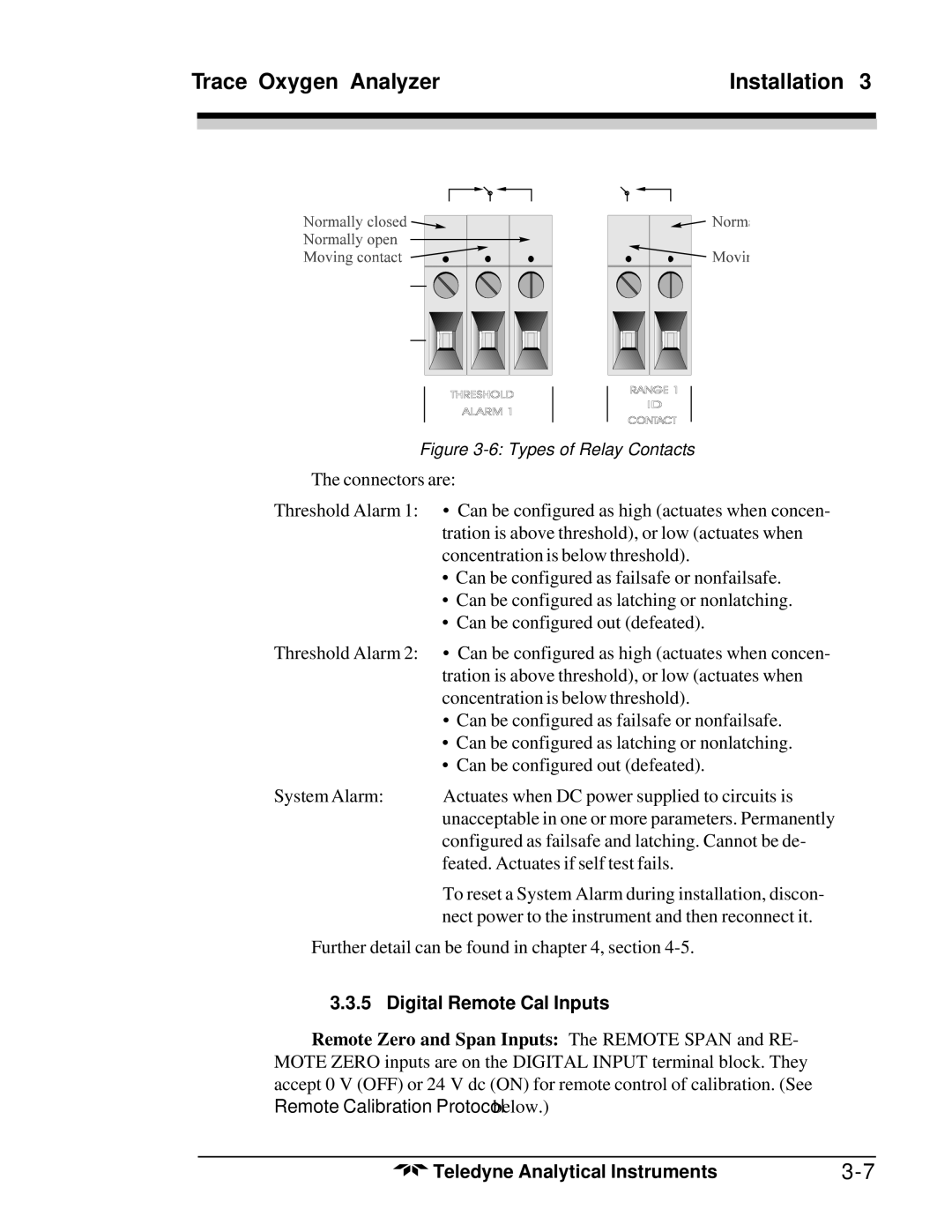
Figure 3-6: Types of Relay Contacts
The connectors are:
Threshold Alarm 1: • Can be configured as high (actuates when concen- tration is above threshold), or low (actuates when concentration is below threshold).
•Can be configured as failsafe or nonfailsafe.
•Can be configured as latching or nonlatching.
•Can be configured out (defeated).
Threshold Alarm 2: | • Can be configured as high (actuates when concen- |
| tration is above threshold), or low (actuates when |
| concentration is below threshold). |
| • Can be configured as failsafe or nonfailsafe. |
| • Can be configured as latching or nonlatching. |
| • Can be configured out (defeated). |
System Alarm: | Actuates when DC power supplied to circuits is |
| unacceptable in one or more parameters. Permanently |
| configured as failsafe and latching. Cannot be de- |
| feated. Actuates if self test fails. |
| To reset a System Alarm during installation, discon- |
| nect power to the instrument and then reconnect it. |
Further detail can be found in chapter 4, section
3.3.5 Digital Remote Cal Inputs
Remote Zero and Span Inputs: The REMOTE SPAN and RE- MOTE ZERO inputs are on the DIGITAL INPUT terminal block. They accept 0 V (OFF) or 24 V dc (ON) for remote control of calibration. (See Remote Calibration Protocol below.)
Teledyne Analytical Instruments |