3 Installation | Model 3020T | |
|
|
|
|
|
|
|
|
|
For safe connections, ensure that no uninsulated wire extends outside of the connectors they are attached to. Stripped wire ends must insert com- pletely into terminal blocks. No uninsulated wiring should be able to come in contact with fingers, tools or clothing during normal operation.
3.3.1 Primary Input Power
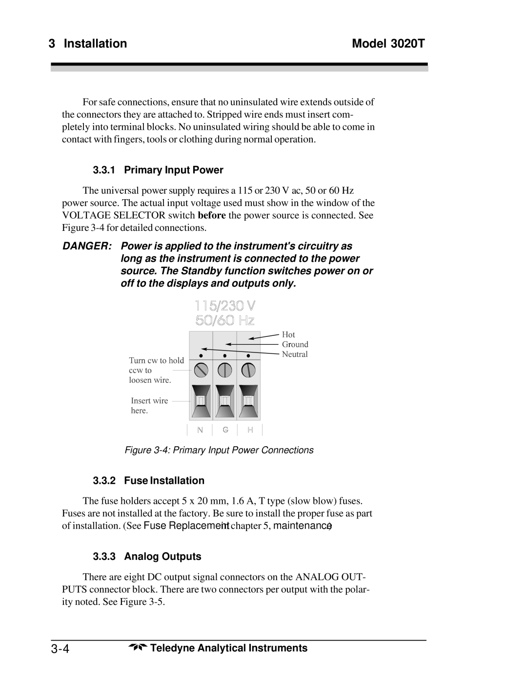
The universal power supply requires a 115 or 230 V ac, 50 or 60 Hz
power source. The actual input voltage used must show in the window of the VOLTAGE SELECTOR switch before the power source is connected. See Figure
DANGER: Power is applied to the instrument's circuitry as long as the instrument is connected to the power source. The Standby function switches power on or off to the displays and outputs only.
Figure 3-4: Primary Input Power Connections
3.3.2 Fuse Installation
The fuse holders accept 5 x 20 mm, 1.6 A, T type (slow blow) fuses. Fuses are not installed at the factory. Be sure to install the proper fuse as part of installation. (See Fuse Replacement in chapter 5, maintenance.)
3.3.3 Analog Outputs
There are eight DC output signal connectors on the ANALOG OUT- PUTS connector block. There are two connectors per output with the polar- ity noted. See Figure
Teledyne Analytical Instruments |