Trace Oxygen Analyzer | Operational Theory | |
|
|
|
2.3.2 Signal Processing
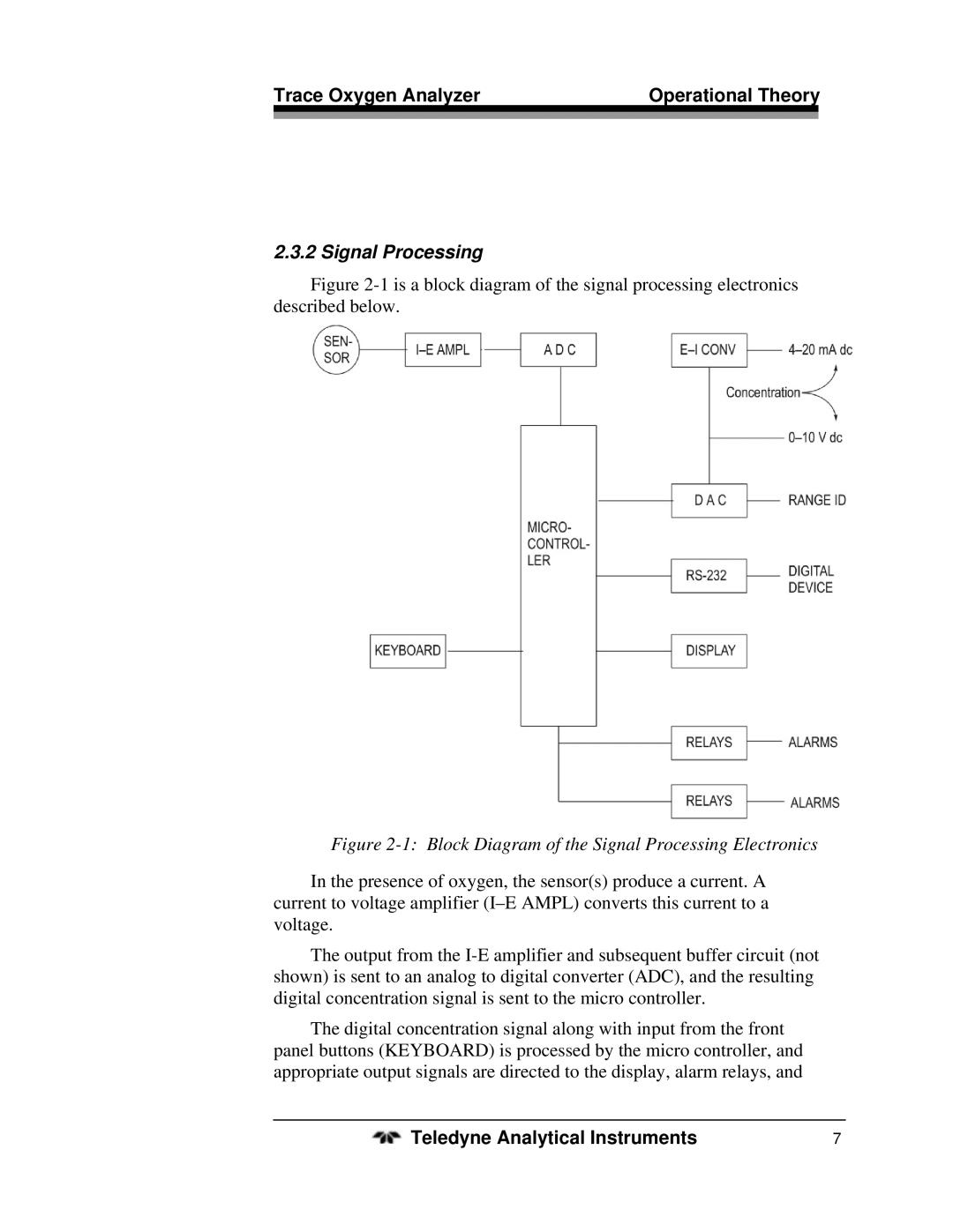
Figure 2-1 is a block diagram of the signal processing electronics described below.
Figure 2-1: Block Diagram of the Signal Processing Electronics
In the presence of oxygen, the sensor(s) produce a current. A current to voltage amplifier
The output from the
The digital concentration signal along with input from the front panel buttons (KEYBOARD) is processed by the micro controller, and appropriate output signals are directed to the display, alarm relays, and
Teledyne Analytical Instruments | 7 |
